28
Vertiv I Liebert LPC I User Manual
2.4
System arrangement during installation
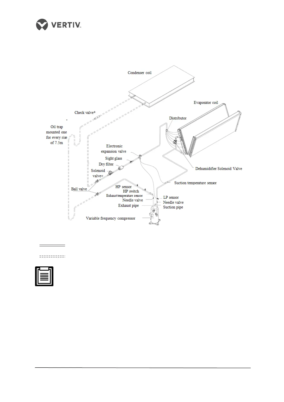
The overall structure and arrangement of a Liebert LPC air conditioner is depicted in Figure
2-11.
Figure 2-11 Overall Layout diagram
• : Factory piping
• : Field piping (by technical personnel)
The following points should be taken into consideration before checking out
the overall layout diagram:
• The single system is used as an example to describe the entire system.
• Vertiv staff and qualified professionals lay out the piping in the laboratory.
• Piping is done by technicians.
• Components (marked with *) are not supplied by Vertiv Co. but are
recommended for proper circuit operation and maintenance.
• Additional components (marked with +) are required when the equivalent
length exceeds 30m.
 Loading...


