50
Vertiv I Liebert LPC I User Manual
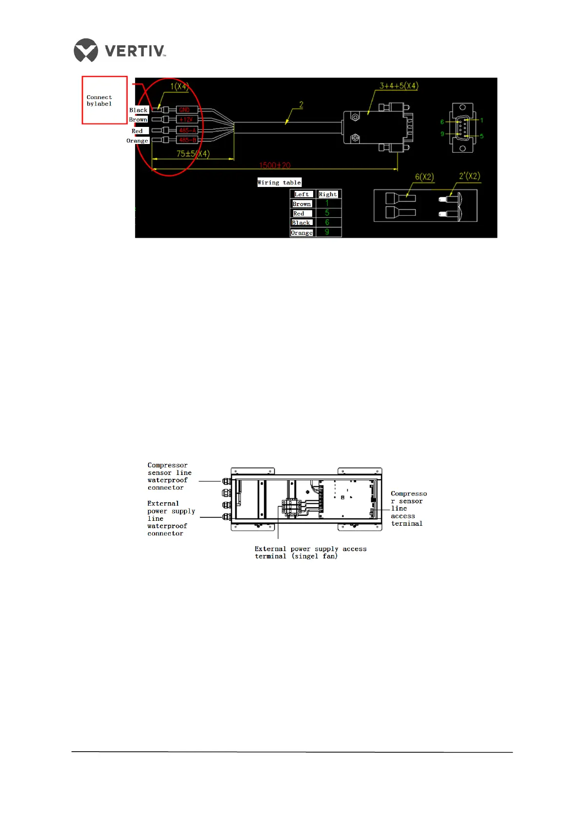
Figure 2-34 On-site installation wiring diagram
2.12.10 Connecting the Solenoid valve of the Pipe Extension kit (Optional)
The Solenoid valve of the pipe extension kit has 2 control cables. These cables are used to
connect to the corresponding terminals of the control board. Refer to the Appendix for the
circuit diagram to understand it at a micro level.
2.12.11 Outdoor Wiring of the Condenser
This section explains the power supply wiring and connections of the control signal terminals
and control signal cables for the condenser:
External power supply wiring
The figure 2-35 depicts the external supply wiring of the condenser:
Figure 2-35 Condenser external power supply wiring
Connecting Condenser Control Signal Terminals
The control signal input terminals for the two circuits of the condenser are #70and #71. The
switching status is similar to that of the compressor.
Connecting Control Signal Cables
Open condenser electrical box sealing plate, showing the fan speed controller board. A
condenser connected to a control signal line wiring as follows:
A signal line required when the compressor enters the condenser through the external
electric power line box waterproof connector, the inner diameter of the joint is φ6mm.

 Loading...


