63
Vertiv I Liebert LPC I User Manual
4.3
Indicators
The controller has built-in indicators, namely- Operation indicator and Alarm Indicator. The
indicators along with their functionalities are defined in the table 4.2.
Table 4.2
Indicator Color Status Function Description
The controller is working properly
Alarm Indicator Red Off No alarm alert
4.4
Control Interface
Once the power is turned on, the LCD screen displays the communication state. If there is no
communication between the controller and target interface board, the LCD will display the
“Communication Failure” notification. However, if the communication is successful, the
screen displays the shutdown or main interface based on the On or Off state of the air
conditioner. The control interface mainly displays the main interface, shutdown interface, and
password.
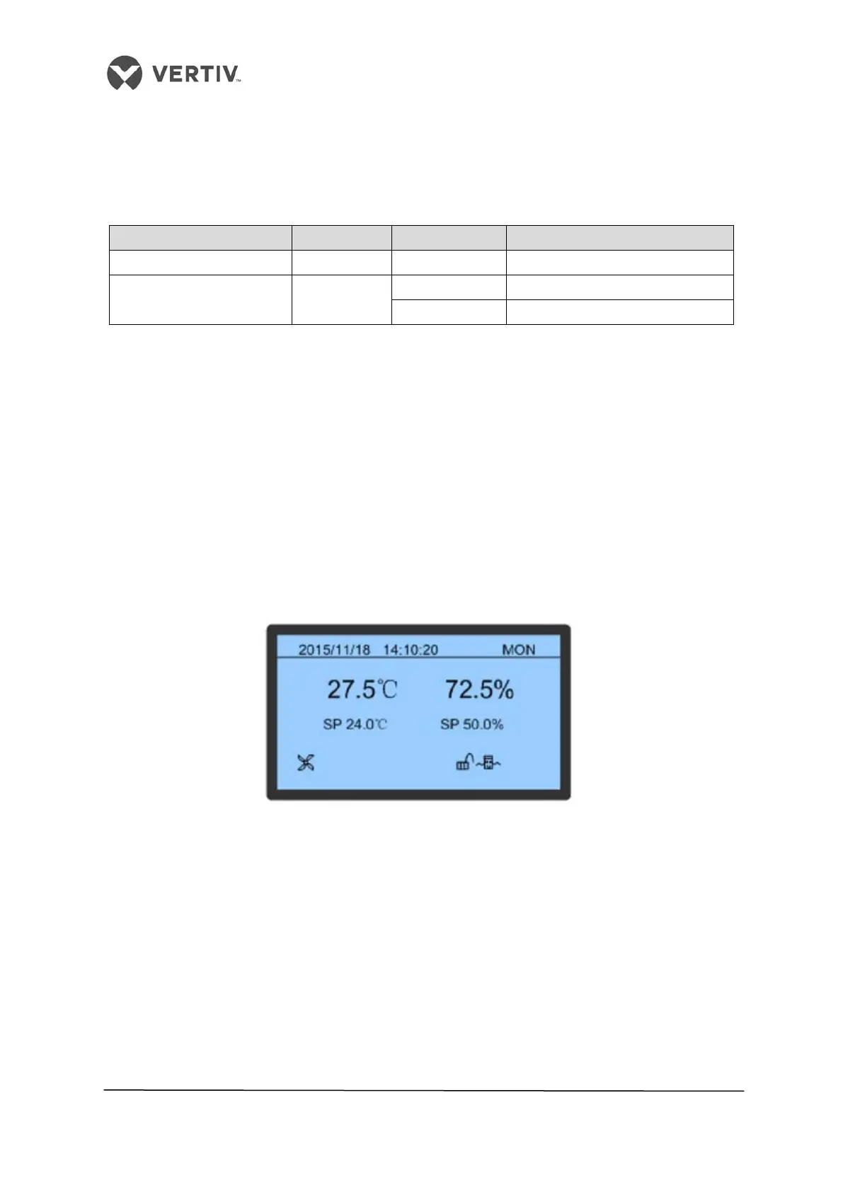
4.4.1 Main interface
Once the air conditioner is powered on wait for the successful communication following
which the main interface will be displayed as depicted in Figure 4-2.
Figure 4-2 Main interface
The Display will be in screen-saver mode in case of no action or if no key is pressed within
the initial 10 minutes. The Blue background display eventually turns off. To work with the
controller, press Enter to view the main menu. On clicking, the main interface displays the
date, time, day of the week, display board address, actual temperature and humidity, humidity
set point, and unit work icons (such as fan, cooling, and on/off standby mode).
The main interface consists of three modes related to the operation of the unit, namely-
• Dynamic Running state icons
• Locking state icons
• On/Off/Standby state icons
 Loading...


