48
Vertiv I Liebert LPC I User Manual
2.12.4 Connecting the Control Cables
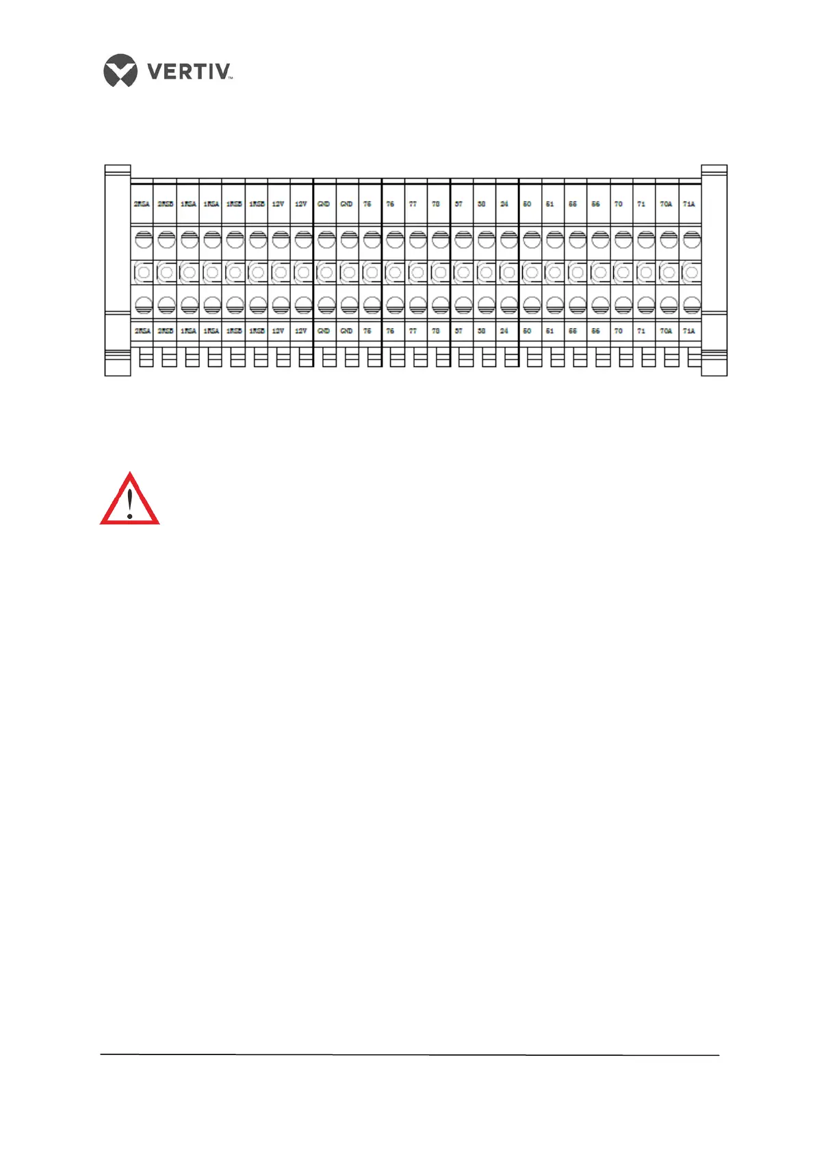
Figure 2-32 shows the amplified version of the field connection terminals.
Figure 2-32 Amplified version of Connection terminals
The upper part of the terminal block is connected to the unit whereas the lower part serves
as the user control signal interfaces.
The connection personnel must take anti-static measures before connecting the
control cables.
2.12.5 Connecting the water-under- floor sensor
• Each unit is equipped with an under-floor sensor. Connect one end of the sensor to
terminal 51# and the other end to the common terminal 24#.
• Though the number of sensors in parallel connection is not limited, each unit has only
one water-under-floor alarm.
2.12.6 Remote Shutdown
As shown in Figure 3-22, 37# and 38# can connect to a remote shutdown switch. These have
been shorted in the factory. The shorting cables must be removed if the terminals are
connected to the remote shutdown switch.
2.12.7 Customized Alarm terminals
• Terminals 50#, 51#, and 56# can be connected to 3 different kinds of sensors and
terminal 24# is their common terminal, defined for smoke and water-under-floor
sensors.
• After the customer terminals are connected with external alarm signals, set the
corresponding customized alarm using the controller.
When the contact is open, the external alarm doesn’t get generated. When the contact gets
closed, the external alarm is generated. In this case, the input state of the customer terminal
 Loading...


