Installation
VTM-2000 Installation and Operation Handbook
2-3
Connecting the VTM-2000
The back panel connectors are illustrated in Figure 2-2, and the function of each
connector is described in Table 2-2.
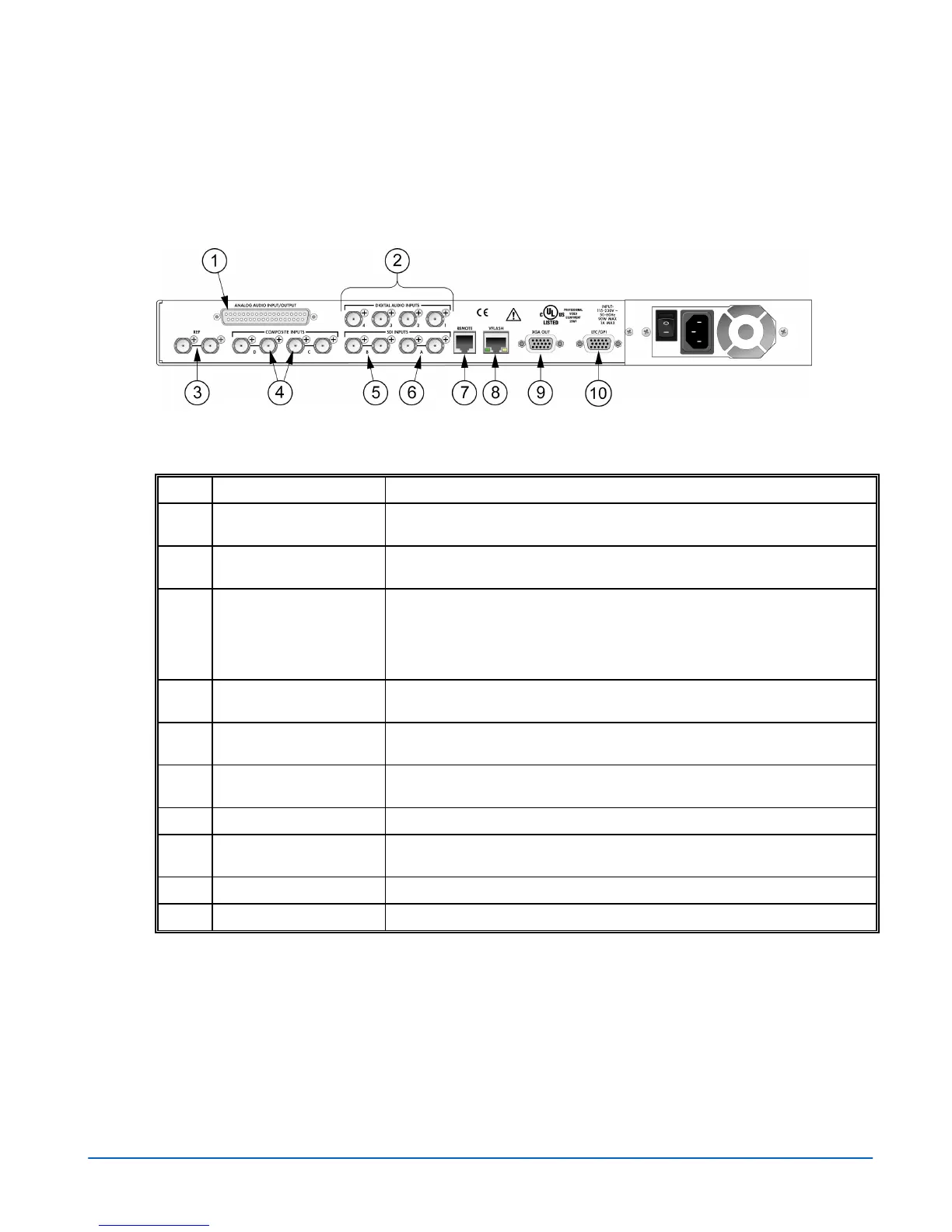
Figure 2-2. VTM-2000 Back Panel Connectors
Table 2-2. Description of Back Panel Connectors
Key Label Description
1
ANALOG AUDIO
IN/OUT
Optional 37-pin, D-sub, male connector for analog audio inputs and outputs.
The supplied breakout board can be used for solderless connections.*
2
DIGITAL AUDIO INPUT
1, 2, 3, 4
Optional female BNC connectors for AES/EBU audio input.
3
REF Female BNC connectors that connect to an external NTSC/PAL reference
signal (video or blackburst) from which the horizontal and vertical sync, and
the color burst frequency for the VTM-2000 will be derived if EXT has been
selected as the REF source. If these connectors are not looped through,
then the unused connector must be terminated at 75Ω.
4
INPUTS C (IN, OUT), D
(IN, OUT)
Female BNC looping analog composite input and output connectors.
Termination required.
5
INPUT B (IN, OUT) Female BNC looping SD SDI input and output connector. Termination
required.
6
INPUT A (IN, OUT) Female BNC looping SD SDI input and output connector. Termination
required.
7
REMOTE RJ11 socket to connect to the remote control panel.*
8
VFlash RJ45, female, 10/100 BaseT Ethernet connection to be used with a PC
running the VFlash program.*
9
XGA OUT 15-pin, high-density, female, D-sub connector for XGA output.*
10
LTC/GPI 15-pin, high-density, female, D-sub connector for LTC, and GPI input.*
*See Appendix C, “Pinouts,” for the connections.