General Operation
VTM-2000 Installation and Operation Handbook
3-15
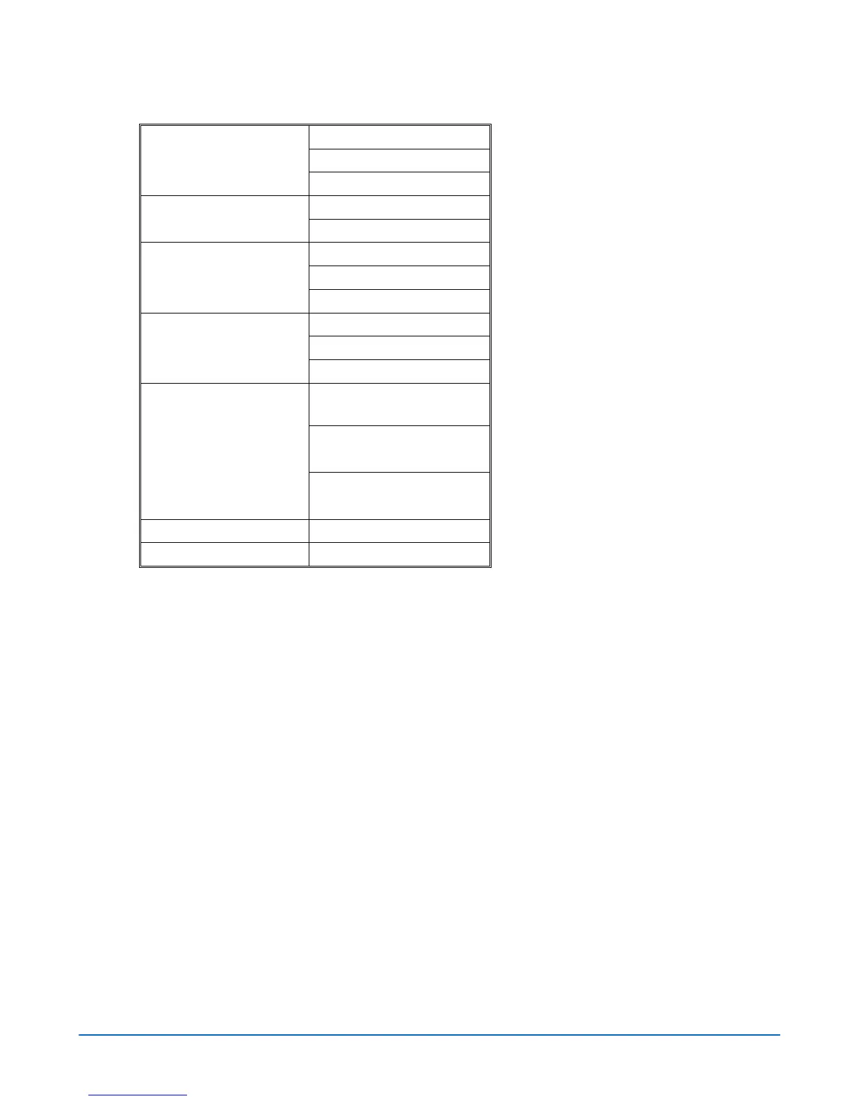
Table 3-9. Waveform (Digital) Menu Structure
FLT (FLAT) (Default)
LP (LOW PASS)
COMPONENT FILTER
BOW (BOWTIE)
PARADE (Default)
PARADE/OVERLAY
OVERLAY
YC
B
C
R
(Default)
RGB
SD FORMAT
YRGB
BLANK ALL (Default)
SHOW SAV/EAV
BLANKING
SHOW ALL
If YC
B
C
R
is selected (Y, C
B
,
C
R
)
If RGB is selected (R, G, B)
COMPONENT
SEQUENCE
If YRGB is selected (Y, R, G
B)
CENTER WAVEFORM
Press SETUP/ENTER
WAVEFORM SETUP
Press SETUP/ENTER
Filter Selection
The filters available are dependent upon the input format. The filters available are:
• Flat: No filtering.
• Low Pass: Selects the Low Pass filter.
• Chroma: Selects the Chroma filter. (Composite only)
• Bowtie: The bowtie filter is used to check the timing relationships between the
digital components. A bowtie test signal is required. (Component only)
• Flat and Low Pass: Flat and Low Pass combination. (Composite only)
Parade and Overlay Selections
Multiple components can be displayed in a single pane.
• When PARADE is selected, the components are shown next to one another (i.e.
Inputs Y, then C
B
, then C
R
in a YC
B
C
R
signal).
• When OVERLAY is selected the components of the input signal are displayed over
each other (i.e. R over G over B in an RGB signal).