Pinouts
VTM-2000 Installation and Operation Handbook
B-4
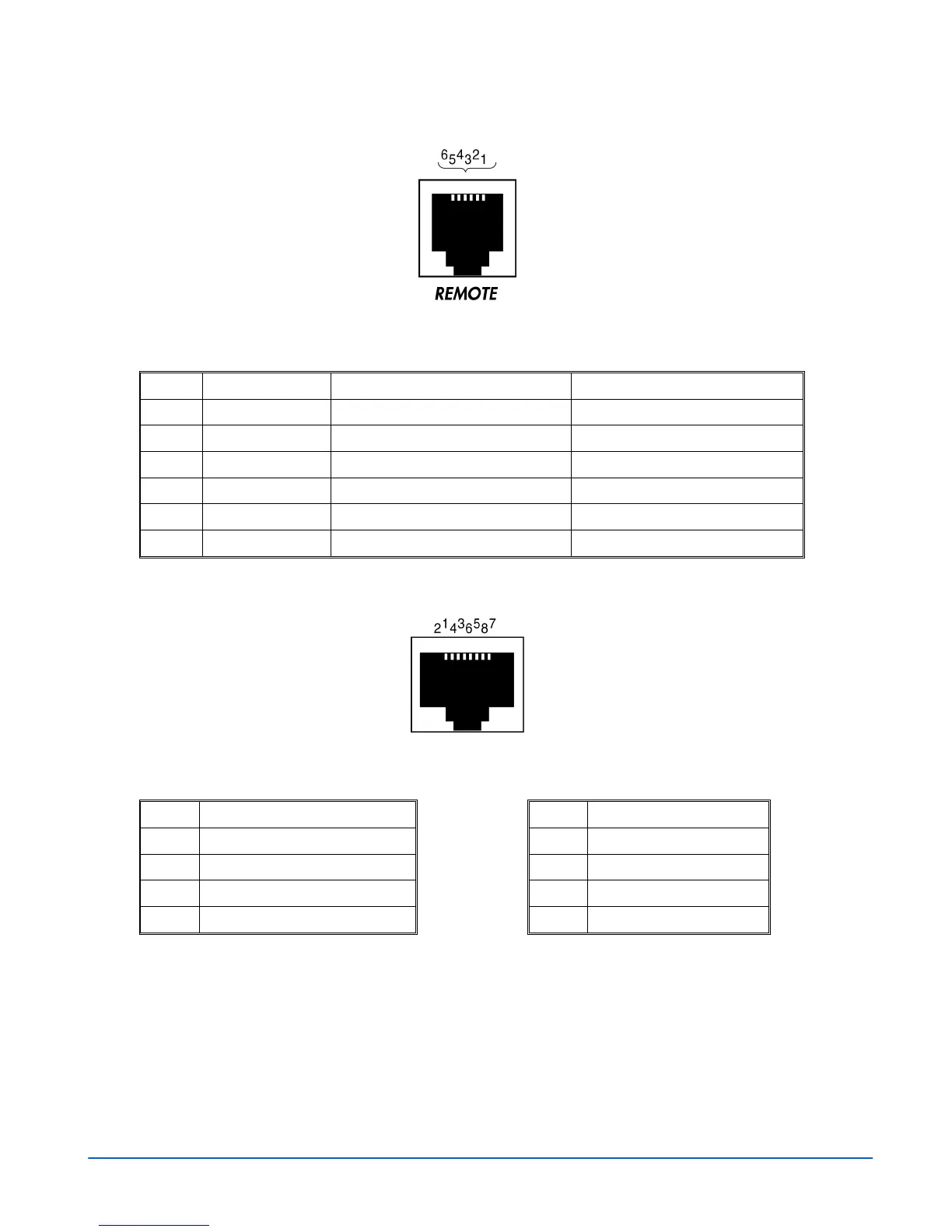
Figure B-5. Remote RJ-11 Control Connector
Table B-4. Remote RJ-11 Control Connector Pinouts
Pinout Signal VTM-2000 RCU-2000
1
OPEN Open GND
2
RX - Received by VTM-2000 Transmit from RCU
3
RX + Received by VTM-2000 Transmit from RCU
4
TX - Transmit from VTM-2000 Received by RCU
5
TX + Transmit from VTM-2000 Received by RCU
6
GND GND GND
Figure B-6. VFlash RJ-45 Connector
Table B-5. VFlash RJ-45 Connector Pinouts
Pinout Signal Pinout Signal
1
TX+
5
N.C.
2
TX-
6
RX-
3
RX+
7
N.C.
4
N.C.
8
N.C.