Chapter 1 Basics and Assembly Manual VIPA System 200V
1-8 HB97E - CPU - RE_21x-1Bx06 - Rev. 13/20
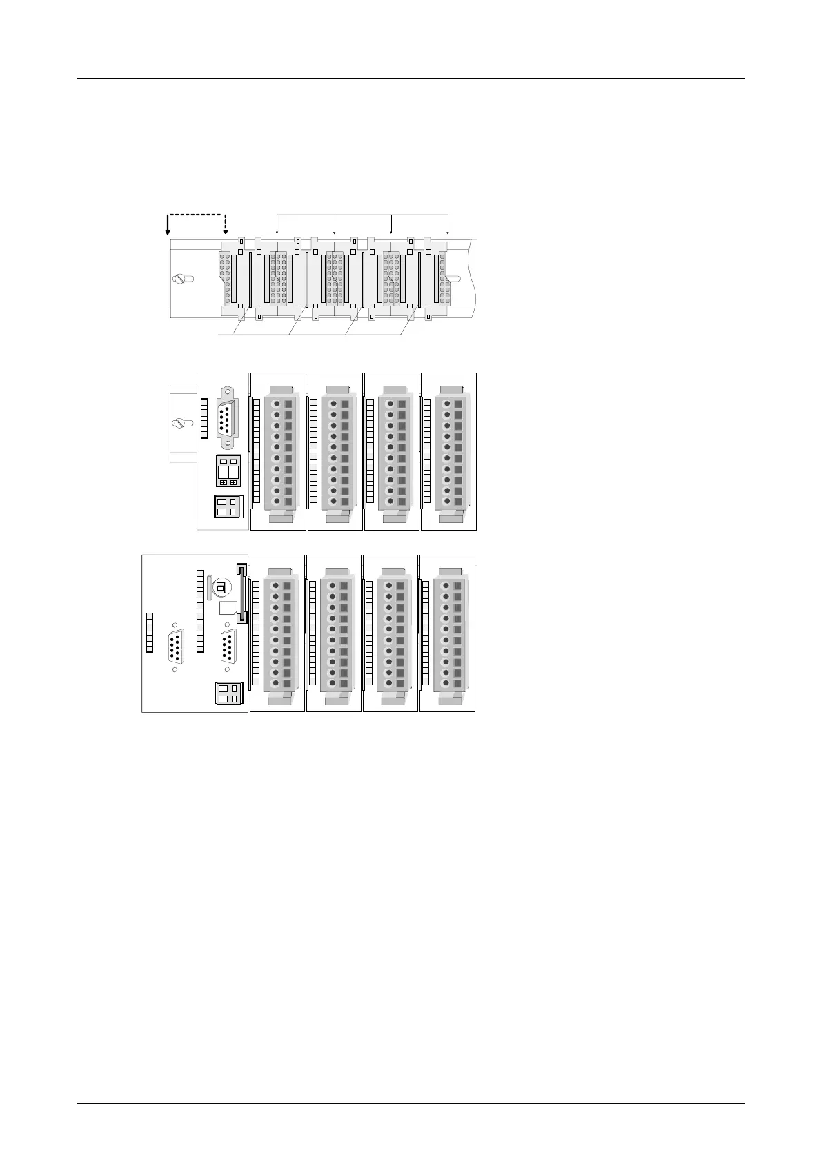
The following figure shows the installation of a 4tier width bus connector in
a profile rail and the slots for the modules.
The different slots are defined by guide rails.
[1] Header module
(double width)
[2] Header module
(single width)
[3] Peripheral module
PW
ER
RD
BA
ADR.
DC24V
+
-
1
2
0
1
1
2
4
3
PW
SF
FC
MC
MMC
R
S
[4] Guide rails
• Use bus connectors as long as possible.
• Sort the modules with a high current consumption right beside the
header module. In the service area of www.vipa.com a list of current
consumption of every System 200V module can be found.
Installation on a
profile rail
Assembly regarding
the current
consumption