Manual VIPA System 200V Chapter 1 Basics and Assembly
HB97E - CPU - RE_21x-1Bx06 - Rev. 13/20 1-9
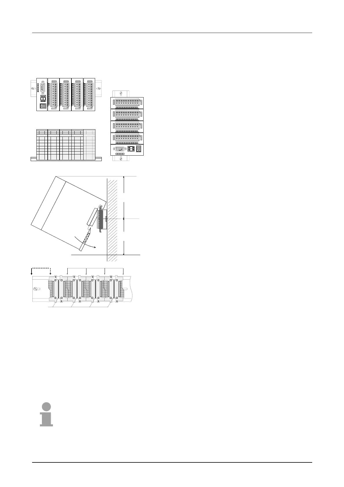
hoizontal assembly
lying assembly
vertical
assembly
01
0
1
Please regard the allowed environmental temperatures:
• horizontal assembly: from 0 to 60°C
• vertical assembly: from 0 to 40°C
• lying assembly: from 0 to 40°C
The horizontal assembly always starts at the left side with
a header module, then you install the peripheral modules
beside to the right.
You may install up to 32 peripheral modules.
80 mm
60 mm
Please follow these rules during the assembly!
• Turn off the power supply before you install or remove
any modules!
• Make sure that a clearance of at least 60mm exists
above and 80mm below the middle of the profile rail.
• Every row must be completed from left to right and it
has to start with a header module.
[1] Header module (double width)
[2] Header module (single width)
12
4
3
[3] Peripheral modules
[4] Guide rails
• Modules are to be installed side by side. Gaps are not
permitted between the modules since this would
interrupt the backplane bus.
• A module is only installed properly and connected
electrically when it has clicked into place with an
audible click.
• Slots after the last module may remain unoccupied.
Note!
A maximum of 32 modules can be connected at the back plane bus. Take
attention that here the maximum sum current of 3.5A is not exceeded.
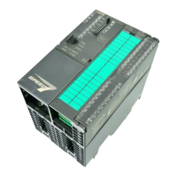
Assembly
possibilities