VIVOTEK - Built with Reliability
User's Manual - 11
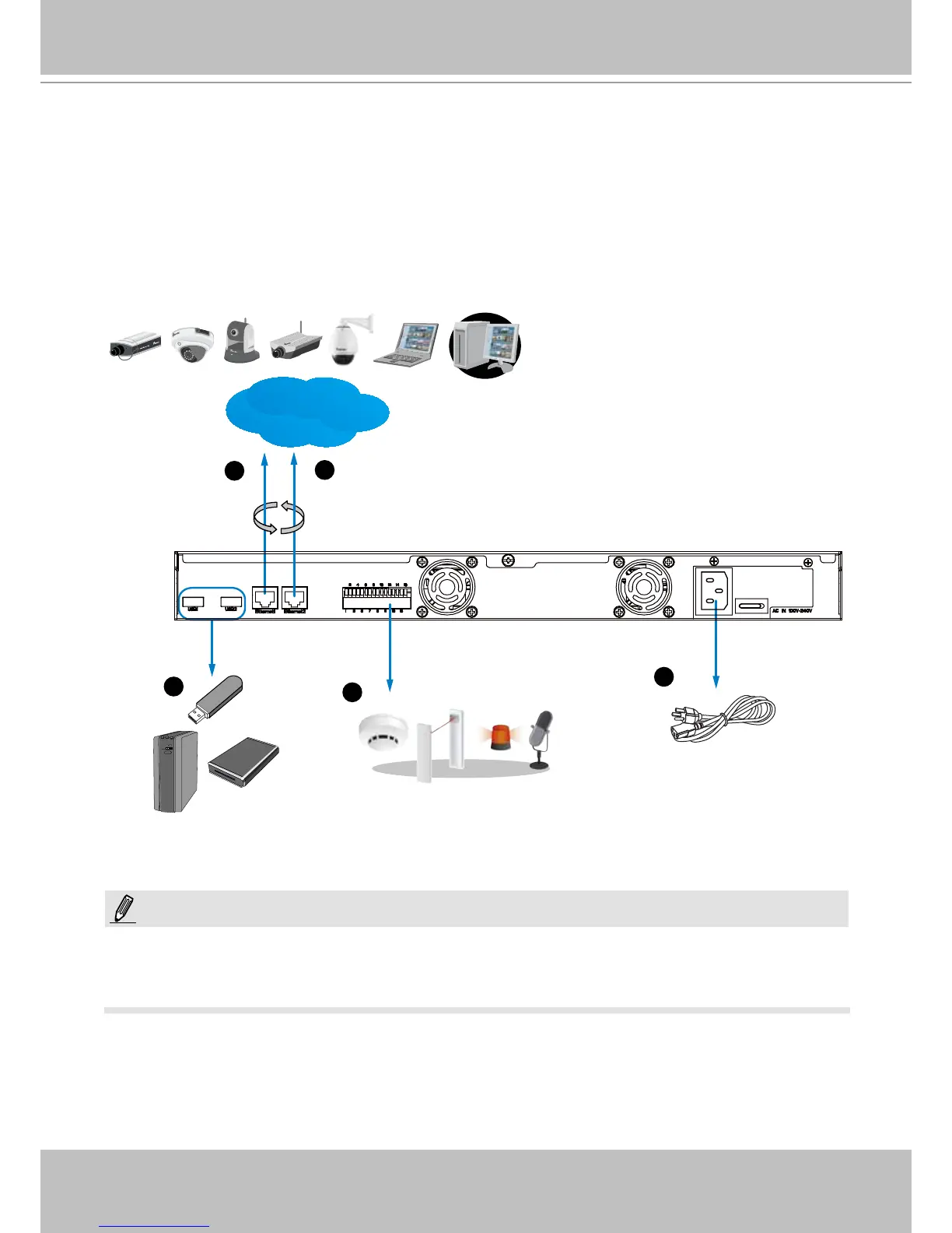
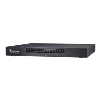
Interface Connections
LAN/WAN
Router
1
2
3
4
5
USB devices
DI/DO devices
Power cord
1 & 2. Connect CAT5e or better-quality Ethernet cables to cameras via a local, switched net-
work, or clients through the Internet. Refer to next page for more information.
3. Connect USB devices such as USB optical drive or UPS.
4. Connect external digital input/output devices to the GPIO teminal block.
5. Make sure the power switch on the rear panel is in the OFF (O) position. Connect the sup-
plied power cord to the power mains (100-240V AC, 50~60Hz).
Cameras and the NVR must reside in the same subnet. Otherwise, the NVR will not be able to
recruit them as a recording conguration.
NOTE: