VIVOTEK - Built with Reliability
User's Manual - 7
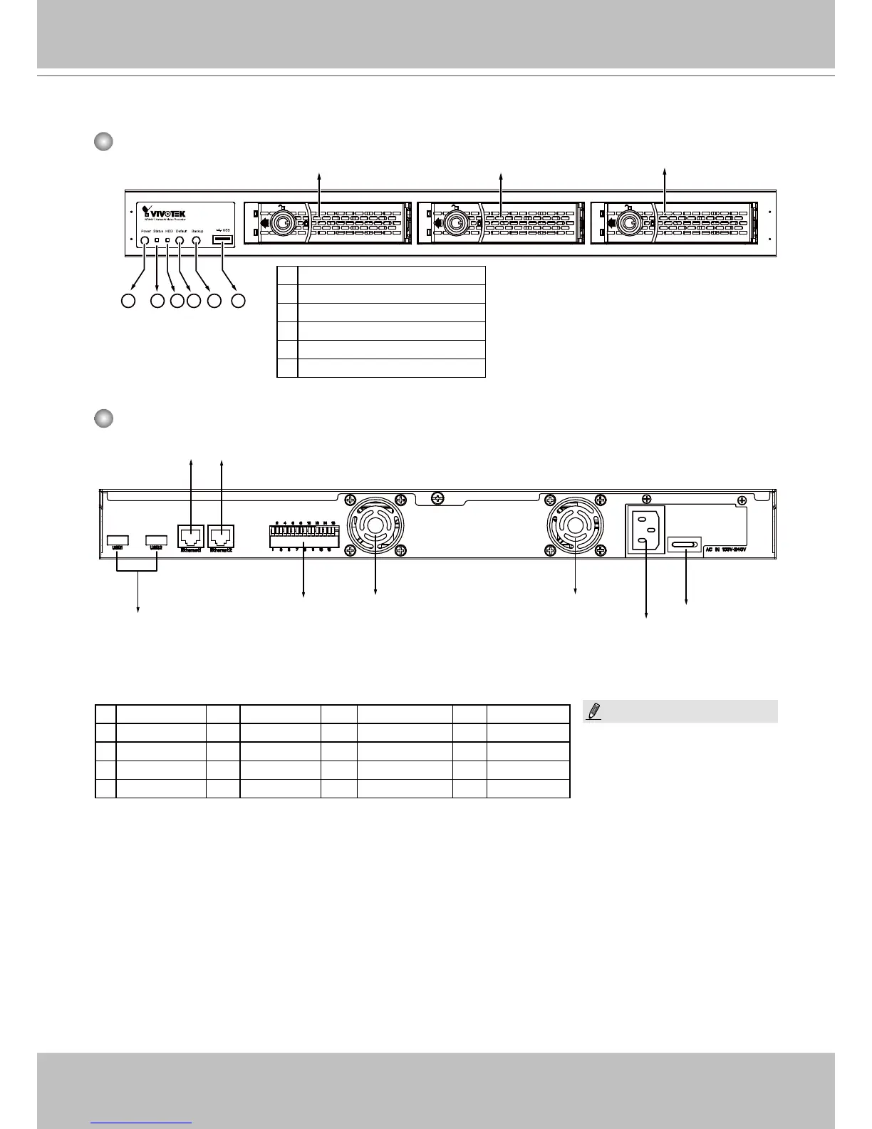
Physical Description
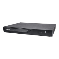
Front View
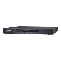
Rear View
1
2 3 4 5 6
Disk 1 Disk 2
1 Power button and LED
2 Status LED
3 HDD activity LED
4 Restore Default button
5 Backup button
6 USB
Disk 3
Disk 4 can be installed inside the
chassis. See page 17 for information.
LAN2 LAN1
USB 1 & 2
GPIO
terminal block
Fan Outlet
Power Cord
Socket
Power Switch
Fan Outlet
1 DO+ (12V) 6 DI2- 11 Power button 16 GND
2 DO- 7 DI3+ 12 GND
3 DI1+ 8 DI3- 13 RS232_TX
4 DI1- 9 DI4+ 14 RS232_RX
5 DI2+ 10 DI4- 15 GND
DI*- (minus) stands for
Ground pins.
NOTE: