VX100Q/VX136Q/VX186Q, VX136QD/VX186QD, VX136QDM2/VX186QDM2
Pos: 134 /Übersc hriften/Überschrif t 3 /Kontrolle u nd Wechsel der Sperr- od er Quenchflüssig keit @ 0\mod_ 110992913998 8_48.doc @ 1 308 @ 3 @ 1
7.1.2 Inspecting and changing the buffer/quenching fluid
Pos: 135 /WBV/P umpen/Wartung/ Sperrkamm er/002 Kontrolle und Wechsel der Sperr-/Q uenchflüssigkeit @ 58\mod_13 12375420472_48. doc @ 308252 @ @ 1
Buffer fluid or quenching fluid
• Check:
After the first 20 operating hours
Every 200 operating hours
Electronic buffer chamber monitoring is possible. Ask us .
• replace:
Every 2000 operating hours
When there is severe contamination
When there is intense leakage, replace the cartridge mechanical seal Chap. “Changing cartridge
mechanical seal"
Chap. “Maintenance plan"
Pos: 136 /WBV/P umpen/Warnhin weise/Hinweis/Hi nweis Versc hmutzung Sperr -oder Quench flüssigkeit @ 41\mod_1273 572187234_48.doc @ 184703 @ @ 1
A slight contamination of buffer/quenching fluid such as a slight rise or fall of buffer/quenching fluid level is
determined by the hydrodynamic lubrication-film of mechanical seal and temperature fluctuations.
Pos: 137 /WBV/P umpen/Warnhin weise/Umwelt/U mweltgerecht e Entsorgung - Sperr- oder Q uenchflüssig keiten @ 61\mo d_13179869600 29_48.doc @ 3 20013 @ @ 1
Environmentally friendly disposal
Treat buffer fluid or quenching fluid, for example, oils and hydraulic fluids, like hazardous waste and dispose
of them properly.
Pos: 138 /Übersc hriften/Überschrif t 3 /Sperr kammeraufbauten @ 1\mod_11 31527994380_4 8.doc @ 5783 @ 3 @ 1
7.1.3 Buffer chamber assemblies
Pos: 139 /WBV/P umpen/Wartung/ Sperrkamm er/002 Sperrkam meraufbau - Pumpe mit druc kbeaufschlagbare m Sperrflüssig keitsbehälter @ 59\mod_1 313570777997_4 8.doc @ 3107 32 @ 4 @ 1
7.1.3.1 Pressurised buffer fluid tank
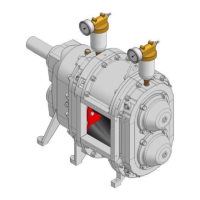
The pressurised buffer fluid tank (hereinafter “tank”) with manual pump ensures a constant and defined
buffer chamber pressure (buffer chamber pressure = tank pressure).
The tank is for safely monitoring the buffer chamber Fig. “Buffer chamber monitoring".
Installing the tank
1. First remove the plug from the buffer chamber. Then completely fill the buffer chamber.
2. Screw the tank directly into the casting of the buffer chamber. Fill the tank about one quarter full.
3. With a manual air pump or via a compressed air connection, set the desired tank pressure.
Tank pressure
The tank pressure should be about 0.5 bar higher than the middle pressure in the pump.
Tank pressure = 0.5 bar + (pressure on the suction side + pressure on the discharge side) / 2
Example
One pump primes with 0.4 bar under pressure and presses with 2.0 bar overpressure.
Pressure on the suction side: – 0.4 bar, pressure on the discharge side: 2.0 bar
Tank pressure = 0.5 bar +
= 1.3 bar
Tank pressure is 1.3 bar.
However, the tank pressure should not exceed 5 bar.


 To Next Page