VX100Q/VX136Q/VX186Q, VX136QD/VX186QD, VX136QDM2/VX186QDM2
Pos: 204 /WBV/P umpen/Warnhin weise/Hinweis/HiFl o plus @ 6 0\mod_13148 68743175_48. doc @ 31414 3 @ @ 1
HiFloplus-rotary lobes, in contrast to HiFlo rotary lobes, have a second groove. The groove, which in the
“arrangement HiFloplus" is not to be used, is marked in red.
Pos: 205 /Übersc hriften/Überschrif t 3 /Drehkol benwechsel - B aureihen VX10 0Q, VX136Q, VX 186Q @ 58\ mod_13128095 51600_48.doc @ 309153 @ 3 @ 1
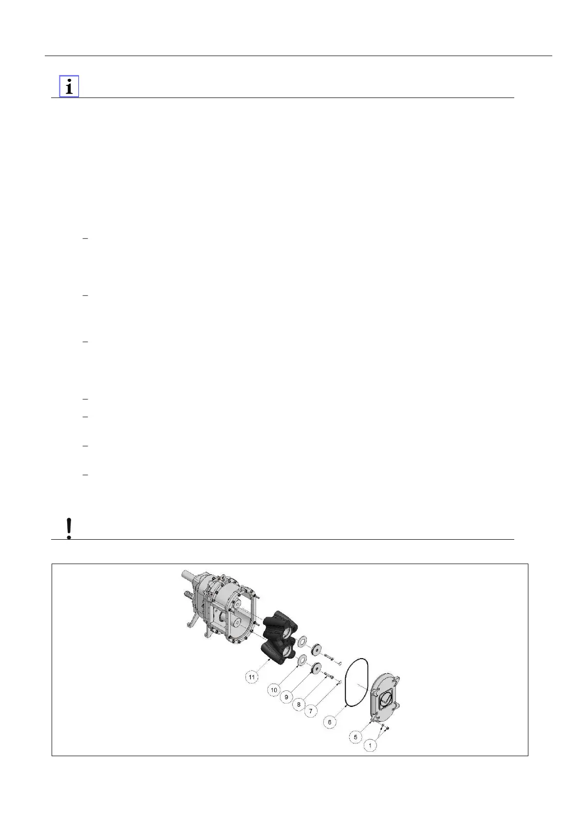
8.7.1 Rotary lobe change - series VX100Q, VX136Q, VX186Q
Pos: 206 /WBV/P umpen/Instandse tzung/002 Kol benwechsel Q-B aureihe @ 58\mod_1312 810307493_48. doc @ 309272 @ @ 1
Fig. “Rotary lobe change, Q series"
1. Open Q cover (5) chap. "Opening the Q cover".
2. Remove plug (7) strain screws (VX136Q, VX186Q) or hex socket head screws (VX100Q) (8) in the
rotary lobes (11). Pull off the pressure disk (9) using a suitable screw (strain screw, hex socket head
screw) or with the threaded rod of the rotary lobe puller remove and the spring washers (10).
With the VVA series with rubberized rotary lobes (not with pure material lobes), the rotary lobe
core is protected by an additional sealing ring in which the pressure disk and spring washers
are located. Remove this sealing ring and reinstall it after the rotary lobe change.
3. Pull the rotary lobes from the shafts using a rotary lobe puller (see spare parts list).
Assemble HiFlo- and HiFloplus-Rotary lobes in pairs, i.e. simultaneously to the upper and the
lower shaft.
4. Install the new rotary lobes in reverse sequence Fig. "HiFlo and HiFloplus arrangement".
Before installing the new rotary lobes, thoroughly clean the mounting surfaces of rotary lobes
and sealing components!
5. With the series VX136Q install two spring washers per shaft with the series, VX100Q and VX186Q
install one spring washer per shaft Fig. "Position of pressure disk ad spring washers".
Make sure that the spring washers are correctly positioned around in the pressure disk.
Carefully press the pressure disk and spring washers into the rotary lobe extension. Spring
washers must not fall into the pulling groove.
Use the strain screw or hex socket head screw to tighten spring washers and pressure disk
chap. “Tightening torques of the hex socket head screw for mounting the pressure disk".
Install plug (7).
6. Close Q cover chap. "Closing the Q cover".
7. Apply pressure to buffer chamber chap. "Buffer chamber".
Pos: 207 /WBV/P umpen/Warn hinweise/Maschi nengefahr/W erkstoff FPM für Dr ehkolben @ 59\mod_1313 063560512_48. doc @ 309787 @ @ 1
Material FPM for rotary lobes
The material 'FPM' for rotary lobes is usable only up to max. 6 bar. Please note the maximum operating
pressure Chap. “Technical data".
Pos: 208 /Grafi ken/Pumpen/ WBV/Instandsetzung /Kolbenwechs el/neu/Drehkol benwechsel Q- Baureihe mit L egende @ 5 9\mod_1313132 994837_48.doc @ 309934 @ @ 1
Fig.
: Rotary lobe change, Q series
Pos: 209 /---Seitenum bruch--- @ 21\mod_12 01696136229 _0.doc @ 805 75 @ @ 1
 Loading...