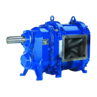
VX100Q/VX136Q/VX186Q, VX136QD/VX186QD, VX136QDM2/VX186QDM2
Pos: 186 /Übersc hriften/Überschrif t 2 /Vor Öffne n des Q oder QD -Deckels @ 59\mod_1313 580281925_48. doc @ 31085 2 @ 2 @ 1
8.2 Before opening the Q or QD cover
Pos: 187 /WBV/P umpen/Instandse tzung/002 Hi nweise vor Öffn en der Deckel @ 58\mod_13 12800871199 _48.doc @ 3090 29 @ @ 1
Before opening the Q and QD cover:
• Depressurise the pump assembly.
• Shut off the connected pipes.
• Empty the pipe as much as possible using drain cocks.
Attention! The remaining liquid flows out of the pump when the cover is opened.
Pos: 188 /Übersc hriften/Überschrif t 2 /Öffnen des Q-Deckels @ 41\mod_12 73581797156_ 48.doc @ 184 910 @ 2 @ 1
8.3 Opening the Q cover
Pos: 189 /WBV/P umpen/Instandse tzung/002 Öff nen des Q-Dec kels @ 58\ mod_1312803144 411_48.doc @ 309093 @ @ 1
Fig. “Q series rotary lobe change"
1. Depressurise buffer chamber (if rotary lobes are to be removed).
2. Loosen hex nuts (1) on the Q cover (5).
3. Remove Q cover and remove the O-ring (6).
Pos: 190 /Übersc hriften/Überschrif t 2 /Schließ en des Q-Deckels @ 41\mod _1273582479882 _48.doc @ 18 4979 @ 2 @ 1
8.4 Closing the Q cover
Pos: 191 /WBV/P umpen/Instandse tzung/002 Sc hließen des Q- Deckels @ 5 8\mod_13128 14886830_48.doc @ 309242 @ @ 1
Fig. “Rotary lobe change, Q series"
1. Thoroughly clean the system surfaces before installing the Q cover (5).
2. Pull the O-ring (6) onto the Q cover.
3. Set the Q cover in place.
4. Screw four hex nuts (1) onto the threaded rods and tighten them. Attention! Do not tilt the Q cover
while doing this, but press it evenly "by hand"! Watch for correct seating of the O-ring.
Pos: 192 /---Seitenum bruch--- @ 21\mod_12 01696136229 _0.doc @ 805 75 @ @ 1


 To Next Page