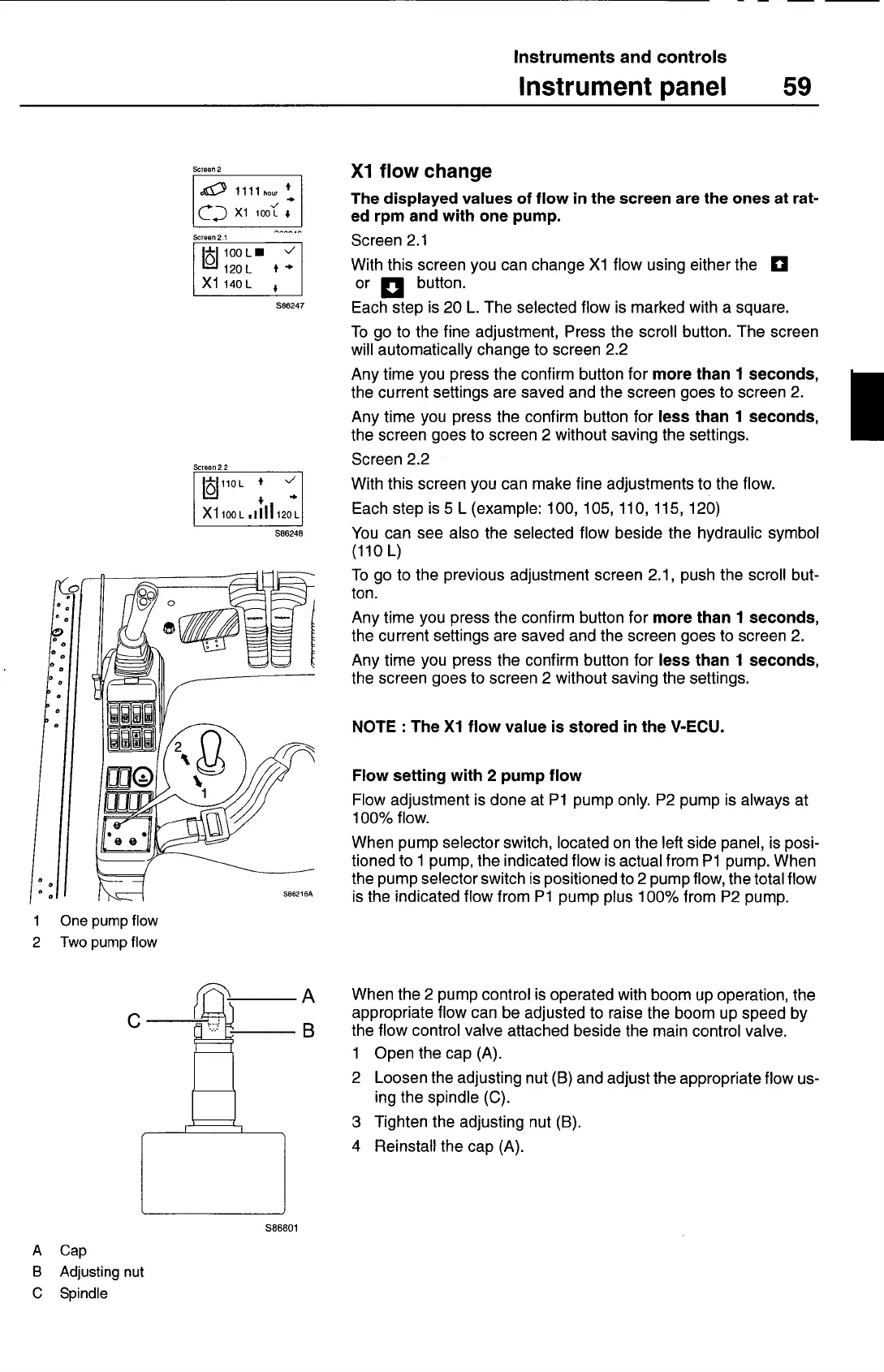
S86216A
Instruments and controls
Instrument panel
59
Screen 2
1111
hoer +
Xl
Screen 2.1
IcI10OL
'J
12OL
++
X1140L
S86247
Screen 22
1Jl1OL
4
+
X1100L •IIlI12OL
S86248
1
One pump flow
2 Twopumpflow
Xl flow change
The displayed values of flow in the screen are the ones at rat-
ed rpm and with one pump.
Screen 2.1
With this screen you can change Xl flow using either the
fl
or
button.
Each step is 20 L. The selected flow is marked with a square.
To go to the fine adjustment, Press the scroll button. The screen
will automatically change to screen 2.2
Any time you press the confirm button for
more than 1 seconds,
the current settings are saved and the screen goes to screen 2.
Any time you press the confirm button for
less than 1 seconds,
the screen goes to screen 2 without saving the settings.
Screen 2.2
With this screen you can make fine adjustments to the flow.
Each step is 5 L (example: 100, 105, 110, 115, 120)
You can see also the selected flow beside the hydraulic symbol
110 L)
To go to the previous adjustment screen 2.1, push the scroll but-
ton.
Any time you press the confirm button for
more than 1 seconds,
the current settings are saved and the screen goes to screen 2.
Any time you press the confirm button for
less than 1 seconds,
the screen goes to screen 2 without saving the settings.
NOTE
:
The Xl flow value is stored in the V-ECU.
Flow setting with 2 pump flow
Flow adjustment is done at P1 pump only. P2 pump is always at
100% flow.
When pump selector switch, located on the left side panel, is posi-
tioned to 1 pump, the indicated flow is actual from P1 pump. When
the pump selector switch is positioned to 2 pump flow, the total flow
is the indicated flow from P1 pump pIus 100% from P2 pump.
S86801
A Cap
B Adjusting nut
C Spindle
A
When the 2 pump control is operated with boom up operation, the
appropriate flow can be adjusted to raise the boom up speed by
B
the flow control valve attached beside the main control valve.
1 Open the cap (A).
2
Loosen the adjusting nut (B) and adjust the appropriate flow us-
ing the spindle (C).
3 Tighten the adjusting nut (B).
4 Reinstall the cap (A).
C
 Loading...