26
6. Thread cutting and automatic feed
6.1 Thread cutting
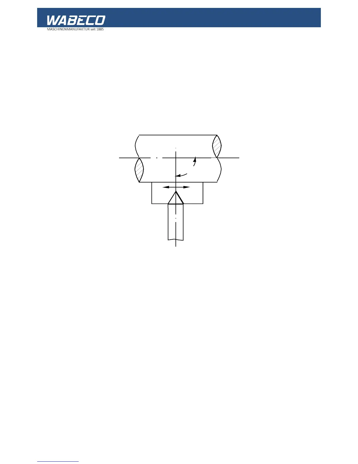
■ The thread turning steel is a moulded turning steel with the profile of the thread to be cut.
■ It is ground according to templates (Figure 1) and must be set precisely to the centre of the work
piece otherwise there will be a distortion in the thread profile.
■ In order to obtain the correct position of thread flanks to the work piece axis, place the grinding
gauge up against the work piece and use it to set the turning steel (Figure 1). To do this, push the
gauge up to both flanks of the turning steel, one after another.
Figure 1: Setting the thread turning steel
Change gears (optional for lathe D2000 and D2400)
■ The change gears belonging to the accessories create the connection between the feed drives and
the lead screw.
■ By fitting different toothed wheel combinations, it is possible to cut metric and imperial right and left
threads.
■ The different axis intervals of the toothed wheels can be set by swivelling the quadrant and
adjusting the quadrant bolt.
Feed:
■ The feed is switched on using the switch lever on the lock plate.
■ The feed must always be switched on in order for the turning steel to return to the same position
when carrying out multiple cutting procedures.
■ After completing the cut, bring the turning steel with the transverse skid out of the inroad otherwise
the flanks and cutting edges will be damaged.
■ Then return the turning steel to the starting position by changing the direction of rotation of the
motor via the turn switch for forwards-reverse.
■ It is good if the thread end has a 4-5 mm wide clearance milled in order to better remove the thread
steel out of the way.
In the event of a long thread diameter, the turning centre point should always be used to prevent the
work piece from pushing away.