20 Installation
1
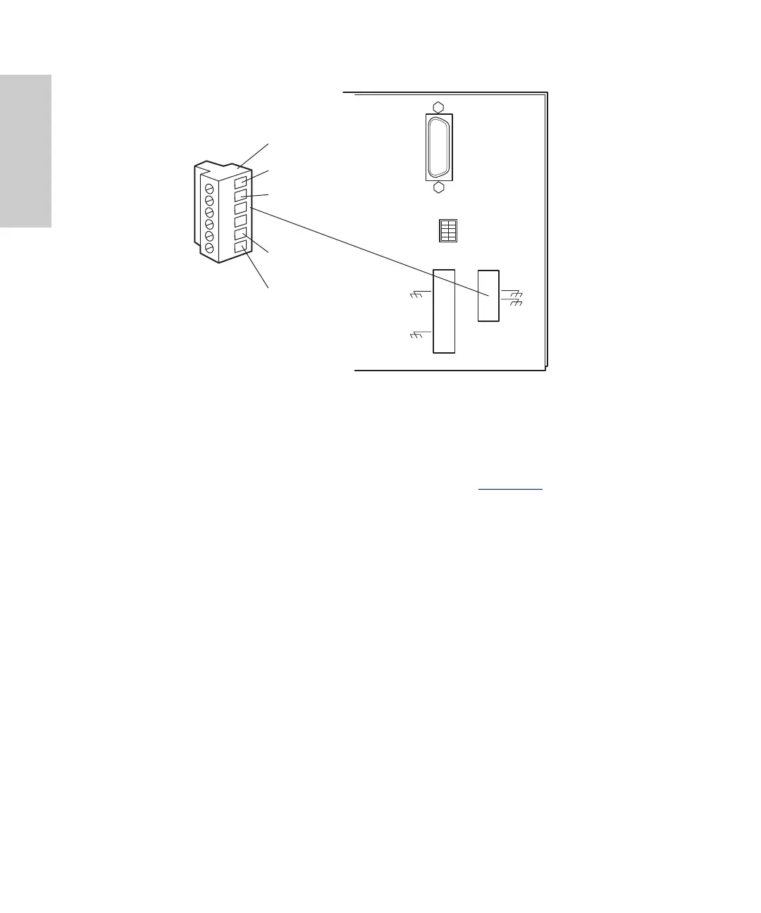
Figure 1-5 Analog Output Terminals
2. Insert the bare wires at one end of an analog signal cable into the positive (
+
)
and negative (–) terminals of Analog Out 1 (see Figure 1-5
). Tighten the two
screws to secure the
+
and – wires.
3. Connect the other end of the analog signal cable to the appropriate analog input
terminal on the external device, being sure to maintain negative-to-negative and
positive-to-positive continuity.
4. Reinstall the Analog Output strip.
1.4.2 Connecting Event Cables
The 996 detector has four terminal strip connections for contact closure signals:
• Two input (inject start) signal terminals
• Two output (programmable event table) signal terminals
If an inject start signal is not available over the IEEE-488 bus, you must provide a signal at
an Event In terminal on the 996 detector rear panel. Manual injectors such as the
Rheodyne 7725i provide a cable that connects the injector to an Event In terminal on the
996 detector rear panel.
123456
IEE 488 ADDRESS
TP01456
Removable Analog Output
Ter min al St rip
+
–
Analog Out 1
+
–
Analog Out 2