124
8. Use the 2-mm Allen wrench to remove the hex screw at the 10 o’clock
position on the switching-valve cartridge.
9. Remove the switching-valve cartridge from the switching-valve
assembly by pulling straight forward.
10. Unpack the replacement switching-valve cartridge.
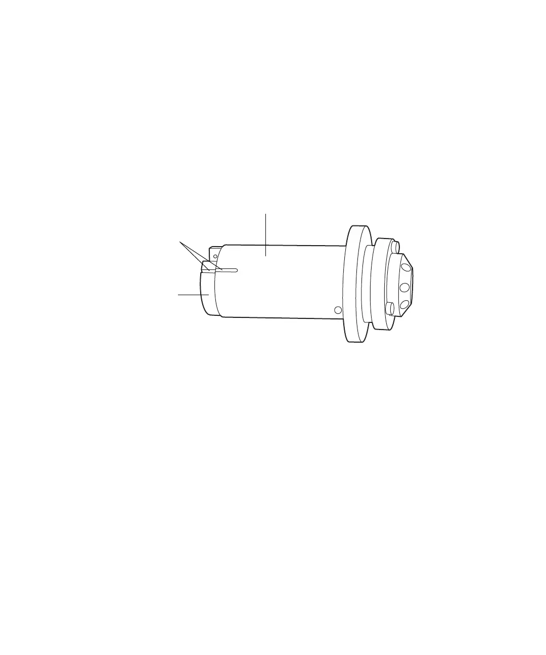
11. Ensure that the groove in the cartridge housing aligns with the groove
on the drive clamp.
Requirement: If the grooves fail to align, turn the drive clamp until they
do so, taking care to avoid scratching the drive clamp or housing.
12. Insert the new switching-valve cartridge into the switching-valve
cartridge chamber.
Requirement: Ensure the new cartridge assumes the same orientation
as the old. It must slide fully into the switching-valve assembly. If it
does not, contact Waters Technical Service.
13. Insert the 2-mm hex screw at the 10 o’clock position on the
switching-valve cartridge, and tighten the screw using the 2-mm Allen
wrench.
14. Pull the valve forward, 1/2 to 3/4 inches, and rotate the lock ring
clockwise until it rests against the stopper.
15. Use the 1/4-inch wrench to reattach all fittings and tighten them
1/4-turn beyond finger-tight for existing fittings, or 3/4-turn beyond
finger-tight for new fittings.
16. Rotate the lock ring counterclockwise to the 12 o’clock position.
17. Push the switching-valve assembly in until it stops.
Switching-valve cartridge housing
Drive clamp
Aligned grooves