EasyManuals Logo

Watts AERCO Benchmark BMK5000 User Manual

Watts AERCO Benchmark BMK5000
213 pages
To Next Page IconTo Next Page
To Previous Page IconTo Previous Page
Page #64 background imageLoading...
Page #64 background image
Benchmark with Edge [I]: Operation-Maintenance Manual
SECTION 4 INITIAL START-UP
OMM-0145_D GF-218 11/2/2020 Technical Support (800) 526-0288 Mon-Fri, 8 am - 5 pm EST Page 64 of 213
11. The main Manual Combustion Calibration screen appears. It provides two methods to
ramp the unit’s valve position up or down:
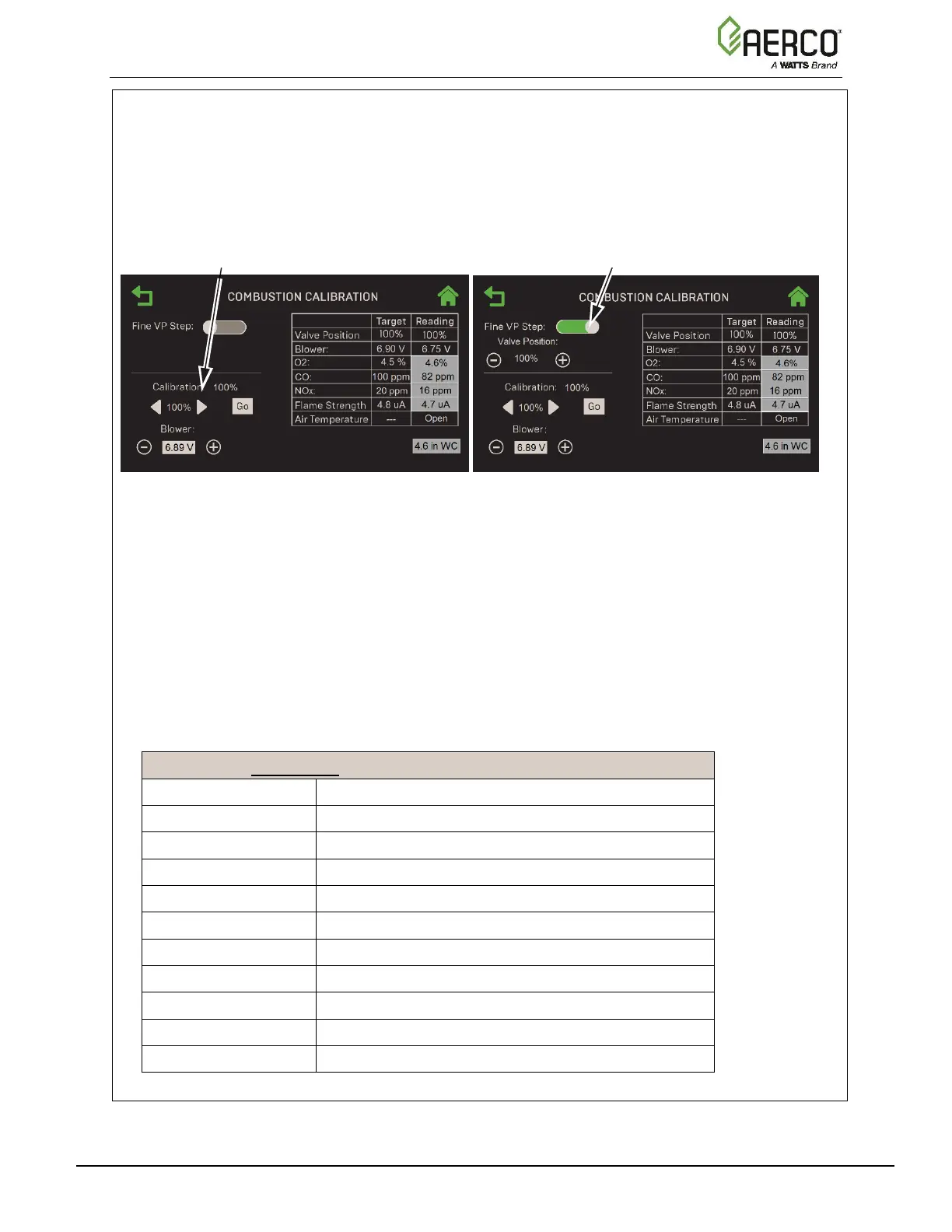
Method 1: Toggle through the pre-set calibration points till you reach the desired
valve position, then press Go to go to that point (left image below).
Method 2: Enable Fine VP Step, then manually press the + or buttons once per
1% to bring the unit to the desired valve position (right image below).
Figure 4-9: Manual Combustion Calibration Screens
12. Set the Controller’s Enable/Disable switch to Enable.
13. Change the valve position to 30%, press the Go button, then verify that the unit has ignited
successfully and is operating as expected.
14. Use the (Right) arrow key to change the valve position to 100%, then press Go.
15. Verify that the gas pressure on the downstream side of the SSOV is within the required
range shown in Table 4-4. If it isn’t, remove the brass hex nut on the SSOV actuator to
access the gas pressure adjustment screw (Figure 4-3). Adjust using a flat-tip screwdriver,
slowly rotating the gas pressure adjustment (in 1/4-turn increments) clockwise to increase
gas pressure or counterclockwise to reduce it. The resulting gas pressure reading on the
downstream manometer should fall in the range listed below.
TABLE 4-4: PROPANE Gas Pressure Range @ 100% Fire Rate
Model
Nominal Gas Pressure
BMK750P
3.9” W.C. ± 0.2W.C. (0.97 kPa ± 0.05 kPa)
BMK1000P
7.6” W.C. ± 0.2W.C. (1.89 kPa ± 0.05 kPa)
1500DF & 1500P
1.4” W.C. ± 0.1W.C. (0.35 kPa ± 0.02 kPa)
2000DF & 2000P
2.5” W.C. ± 0.1W.C. (0.62 kPa ± 0.02 kPa)
2500DF & 2500P
2.0” W.C. ± 0.1W.C. (0.50 kPa ± 0.02 kPa)
3000DF & 3000P
1.6” W.C. ± 0.1W.C. (0.40 kPa ± 0.02 kPa)
4000DF & 4000P
1.5” W.C. ± 0.1W.C. (1.12 kPa ± 0.02 kPa)
5000NDF & 5000NP
1.5” W.C. ± 0.1W.C. (1.12 kPa ± 0.02 kPa)
5000DF & 5000P
2.0” ± 0.2” W.C. (0.50 to 0.05 kPa)
6000DF & 6000P
4.2” ± 0.2” W.C. (1.05 to 0.05 kPa)
PRE-SET CALIBRATION CONTROLS
VALVE POSITION CONTROLS

Table of Contents

Other manuals for Watts AERCO Benchmark BMK5000

Questions and Answers:

Question and Answer IconNeed help?

Do you have a question about the Watts AERCO Benchmark BMK5000 and is the answer not in the manual?

Watts AERCO Benchmark BMK5000 Specifications

General IconGeneral
BrandWatts
ModelAERCO Benchmark BMK5000
CategoryBoiler
LanguageEnglish

Related product manuals