6 | CFW701
English
General Instructions
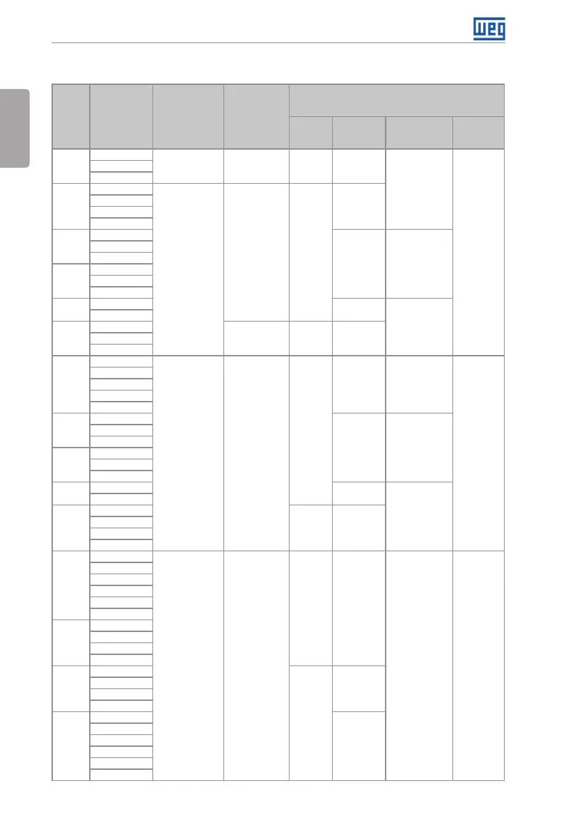
Table 2.2: Options available for each model according to the frame size, power supply, rated current and
voltage of the inverter
Frame
Size
Rated Output
Current for
ND Overload
Number of
Power Phases
Rated Voltage
Available Options for the Remaining Identification
Codes of the Inverters
(standard product is shown in bold)
Braking
Enclosure
(protection
degree)
Disconnecting
Switch
Conducted
Emission
Level
A (IP20)
B (IP55)
06P0 = 6.0 A
S = Single-phase 2 = 200…240 V DB
20, 21, N1
or 55
Blank
C3
07P0 = 7.0 A
10P0 = 10 A
A (IP20)
B (IP55)
07P0 = 7.0 A
T = three-phase
2 = 200…240 V DB
20, 21, N1
or 55
10P0 = 10 A
13P0 = 13 A
16P0 = 16 A
B
24P0 = 24 A
20, 21, N1
or 55
Blank or DS
28P0 = 28 A
33P5 = 33.5 A
C
45P0 = 45 A
54P0 = 54 A
70P0 = 70 A
D
86P0 = 86 A
21, N1 or 55
Blank or DS
0105 = 105 A
E
0142 = 142 A
2 = 220 / 230 V NB or DB 20, N1 or 55
0180 = 180 A
0211 = 211 A
A (IP20)
B (IP55)
03P6 = 3.6 A
T = three-phase 4 = 380...480 V
DB
20, 21, N1
or 55
Blank
C3
05P0 = 5.0 A
07P0 = 7.0 A
10P0 = 10 A
13P5 = 13.5 A
B
17P0 = 17 A
20, 21, N1
or 55
Blank or DS
24P0 = 24 A
31P0 = 31 A
C
38P0 = 38 A
45P0 = 45 A
58P5 = 58.5 A
D
70P5 = 70.5 A
21, N1 or 55
Blank or DS
88P0 = 88 A
E
0105 = 105 A
NB or DB 20, N1 or 55
0142 = 142 A
0180 = 180 A
0211 = 211 A
B
02P9 = 2.9 A
T = three-phase 5 = 500...600 V
DB 20, 21 or N1
Blank C3
04P2 = 4.2 A
07P0 = 7.0 A
10P0 = 10 A
12P0 = 12 A
17P0 = 17 A
C
22P0 = 22 A
27P0 = 27 A
32P0 = 32 A
44P0 = 44 A
D
22P0 = 22 A
NB or DB
20, 21 or N1
27P0 = 27 A
32P0 = 32 A
44P0 = 44 A
E
53P0 = 53 A
20 or N1
63P0 = 63 A
80P0 = 80 A
0107 = 107 A
0125 = 125 A
0150 = 150 A