CFW701 | 13
Installation and Connection
English
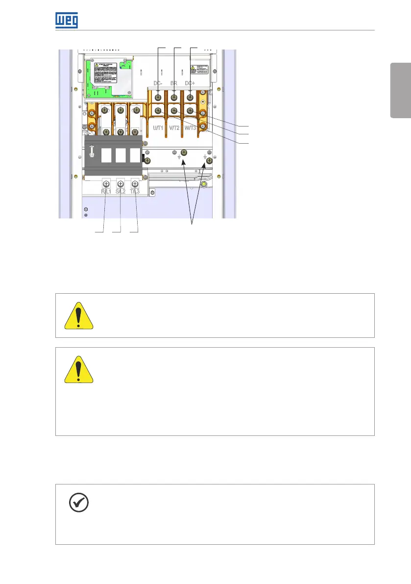
R/L1 S/L2 T/L3
DC- DC+
U/T1
V/T2
W/T3
BR
Ground
(f) Frame size E with degree of protection IP55 and
disconnect switch
Figure 3.1: (a) to (f) Power terminals and grounding points – frame sizes A to E
3.2.2 Power / Grounding Wiring and Fuses
ATTENTION!
Use proper cable lugs for the power and grounding connection cables.
ATTENTION!
Residual Current Device (RCD):
When installing an RCD to guard against electrical shock, only devices with
a trip current of 300 mA should be used on the supply side of the inverter.
Depending on the installation (motor cable length, cable type, multimotor
configuration, etc.), the RCD protection may be activated. Contact the RCD
manufacturer for selecting the most appropriate device to be used with
inverters.
Refer to Table B.1 on page 151, Table B.2 on page 152 and Table B.3 on page 153 for
the recommended wiring and fuses and Table B.6 on page 165 for the specifications of the
power terminals.
NOTE!
The gauges values presented in Table B.1 on page 151, Table B.2 on page
152 and Table B.3 on page 153 are for reference only. Installation conditions
and the maximum permitted voltage drop shall be considered for the proper
wiring sizing.