CFW701 | 23
Installation and Connection
English
3. Shielded output cables (motor cables) and connect the shield at both ends (motor and
inverter) with a low impedance connection for high frequency. Use PCSx-01 kit supplied
with frame sizes A, B and C inverters. For frame sizes B and C with degree of protection
IP55, use the PCSC-03 shield kit. For frame sizes D and E inverters use the clamps supplied
with the product. Ensure good contact between the cable shield and the clamps. Refer to
Figure 3.4 on page 18 and keep the proper separation from other cables according to
Item 3.2.6 Cable Distances on page 22. The maximum motor cable length and conduction
and radiated emission levels are presented at Table B.7 on page 168. Use an external RFI
filter at the input of the inverter if necessary to have a lower emission level and/or a longer
motor cable length. For more information (RFI filter commercial reference, motor cable
length and emission levels) refer to Table B.7 on page 168.
4. Shielded control cables and separate the remaining cables according to Item 3.2.6 Cable
Distances on page 22.
5. Inverter grounding according to the instructions on Item 3.2.4 Grounding Connections on
page 18.
6. Grounded power supply.
3.3.2 Emission and Immunity Levels
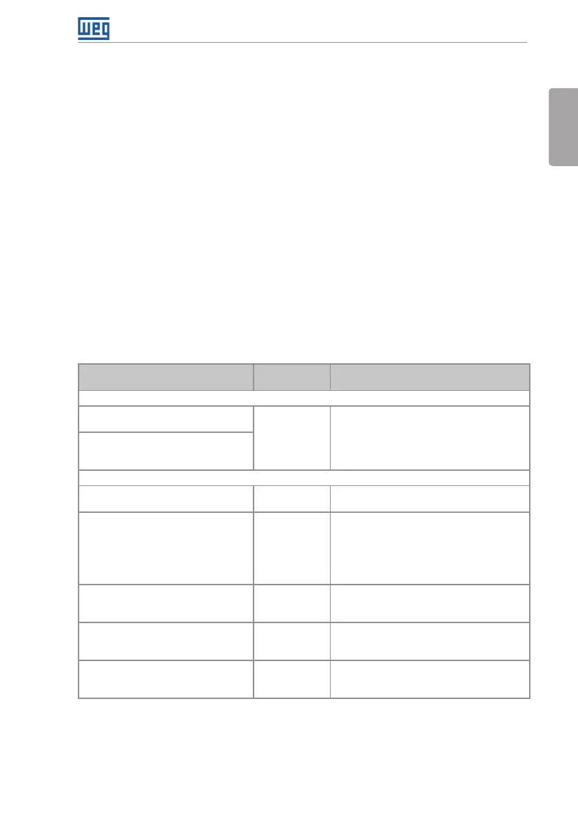
Table 3.3: Emission and immunity levels
EMC Phenomenon
Basic
Standard
Level
Emission:
Mains Terminal Disturbance Voltage
Frequency Range: 150 kHz to 30 MHz).
IEC/EN61800-3
It depends on the inverter model and the
motor cable length.
See Table B.6 on page 165.
Electromagnetic Radiation Disturbance
Frequency Range: 30 MHz to 1000
MHz).
Immunity:
Electrostatic Discharge (ESD). IEC 61000-4-2
4 kV for contact discharge and 8 kV for air
discharge.
Fast Transient-Burst. IEC 61000-4-4
2 kV / 5 kHz (coupling capacitor) power input
cables.
1 kV / 5 kHz control cables, and remote
keypad cables.
2 kV / 5 kHz (coupling capacitor) motor
output cables.
Conducted Radio-Frequency Common
Mode.
IEC 61000-4-6
0.15 to 80 MHz; 10 V; 80 % AM (1 kHz).
Power supply cable, motor, control and
remote keypad (HMI).
Surge Immunity. IEC 61000-4-5
1.2/50 μs, 8/20 μs.
1 kV line-to-line coupling.
2 kV line-to-ground coupling.
Radio-Frequency Electromagnetic
Field.
IEC 61000-4-3
80 to 1000 MHz.
10 V/m.
80 % AM (1 kHz).
Refer to Table B.7 on page 168 for conducted and radiated emission levels accomplished
with and without external RFI filter. The reference model for the external filter is also presented.