18 | CFW701
Installation and Connection
English
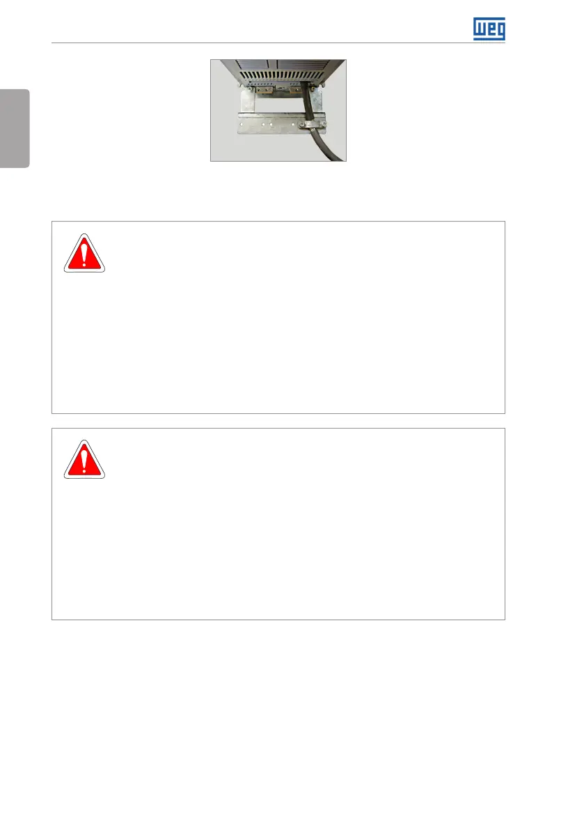
Figure 3.4: Motor cable shielding connection with PCSx-01 accessory
3.2.4 Grounding Connections
DANGER!
The inverter shall be connected to a Protective Ground (PE).
Use the minimum ground wiring gauge as indicated in the Table B.1 on page
151, Table B.2 on page 152 and Table B.3 on page 153.
Connect the inverter grounding connections to a ground bus bar, to a single
ground point, or to a common grounding point (impedance ≤ 10 Ω).
The neutral conductor of the network shall be solidly grounded; however,
this conductor shall not be used to ground the inverter.
It is necessary to use a copper cable with 10 mm
²
minimum or 2 cables with
the same wire gauge as specified in Table B.1 on page 151, Table B.2 on
page 152 and Table B.3 on page 153 for connecting the inverter to the
ground protection to be in accordance with IEC61800-5-1 since the leakage
current is greater than 3.5 mA AC.
DANGER!
Le variateur doit être raccordé à une terre de protection (PE).
Utilisez la section minimale de raccordement à la terre indiquée dans les Table
B.1 à la page 151, Table B.2 à la page 152 et Table B.3 on page 153.
Connectez la masse du variateur à une barre c llectrice de terre en un seul
point ou à un point commun de raccordement à la terre (impédance ≤ 10 Ω).
Le conducteur neutre doit être solidement raccordé à la terre; néanmoins,
ce conducteur ne doit pas s'utiliser pour raccorder le variateur à la terre.
Il est nécessaire d'utiliser un câble de section minimale 10 mm
²
ou 2 câbles
de section identique (voir les Table B.1 à la page 151, Table B.2 on page
152 et Table B.3 on page 153 pour raccorder le variateur à la terre
conformément à la norme IEC61800-5-1 du fait que le courant de fuite
alternatif est supérieur à 3.5 mA.