CFW701 | 19
Installation and Connection
English
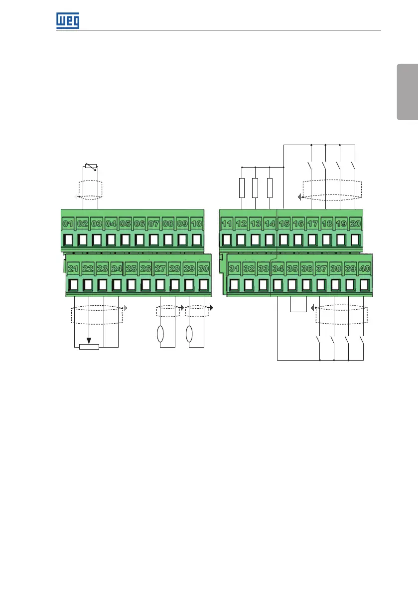
3.2.5 Control Connections
The control connections (analog inputs/outputs and digital inputs/outputs), shall be performed
in connector XC1 of the CC701 control board. Functions and typical connections are presented
in Figure 3.5 on page 20.
GND (24 V)
REF+
AI1+
AI1-
REF-
AO1
AO2
AGND (24 V)
AGND (24 V)
AI2+
AI2-
A (-) – RS-485
DO3
DO4
DO5
+24 V
+24 V
COM
GND (24 V)
RL1-NA
RL1-C
RL2-C
RL2-NA
DI5
DI1
DI6
DI2
DI7
DI3
DI8
DI4
>300 Ω
>300 Ω
>300 Ω
B (+) – RS-485
GND
AI3-
AI3+
NC
NC
NC
PTC
≥5 kΩ
Active high digital inputs
(1)
(1) Refer to Figure 3.5 on page 20 for active low digital inputs connection.
(a) Active high digital inputs
rpm
amp