20 | CFW701
Installation and Connection
English
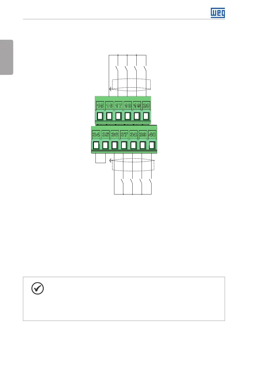
+24 V
GND (24 V)
DI5
DI6
DI7
DI8
Active low digital inputs
+24 V
COM
GND (24 V)
DI1
DI2
DI3
DI4
(b) Active low digital inputs
Figure 3.5: (a) and (b) XC1 connection terminals
Refer to Figure A.3 on page 141 to find the control board, the XC1 connector (control signals),
the S1 DIP-switches (to select the type of signal of the analog inputs and outputs) and S2
(RS-485 network termination) and slots 3 and 5 for accessories (see Section 7.2 ACCESSORIES
on page 38).
The CFW701 inverters are supplied with the digital inputs configured as active high and the
analog inputs and outputs configured for voltage signal 0...10 V.
NOTE!
To be able to use the analog input and/or output as current signals, it is
necessary to change the switch S1 and the related parameters as per Table
3.1 on page 21. In order to set the analog inputs to bipolar voltage signal
(-10…10 V), it is necessary to set P0233 and P0238 according to Table 3.1 on
page 21. Refer to the CFW701 programming manual for more information.