CFW701 | 21
Installation and Connection
English
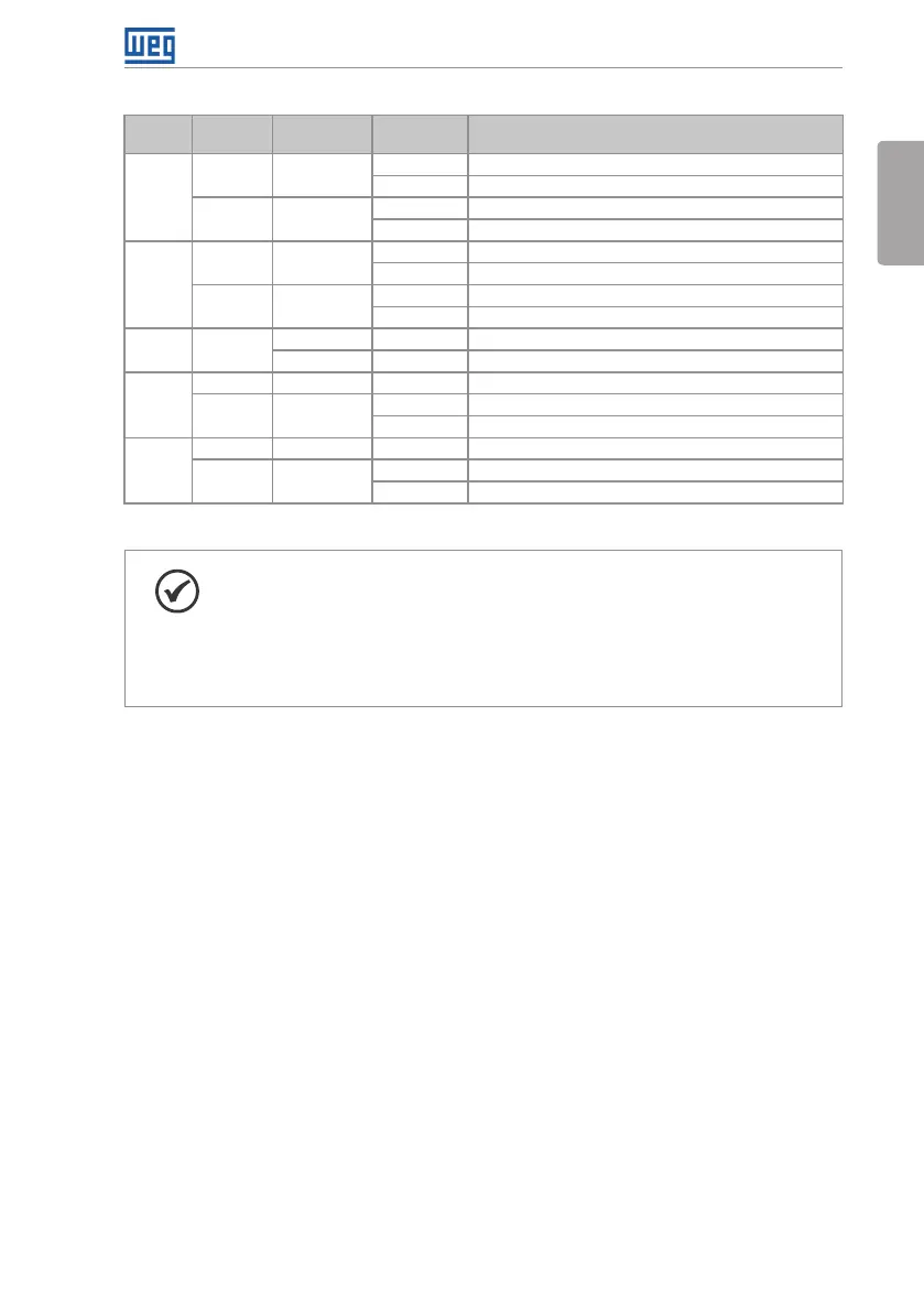
Table 3.1: Configuration of the switch for the analog input and output signals selection
Input/
Output
Signal
S1 Switch
Settings
Signal
Range
Parameter Settings
AI1
Voltage S1.2 = OFF
(*)
0…10 V
(*)
P0233 = 0 (direct reference) or 2 (reverse reference).
-10…10 V P0233 = 4
Current S1.2 = ON
0...20 mA P0233 = 0 (direct reference) or 2 (reverse reference).
4...20 mA P0233 = 1 (direct reference) or 3 (reverse reference).
AI2
Voltage S1.1 = OFF
(*)
0…10 V
(*)
P0238 = 0 (direct reference) or 2 (reverse reference).
-10…10 V P0238 = 4
Current S1.1 = ON
0...20 mA P0238 = 0 (direct reference) or 2 (reverse reference).
4...20 mA P0238 = 1 (direct reference) or 3 (reverse reference).
AI3 Current
- 0...20 mA P0243 = 0 (direct reference) or 2 (reverse reference).
- 4...20 mA P0243 = 1 (direct reference) or 3 (reverse reference).
AO1
Voltage S1.3 = ON
(*)
0...10 V
(*)
P0253 = 0 (direct reference) or 2 (reverse reference).
Current S1.3 = OFF
0...20 mA P0253 = 0 (direct reference) or 2 (reverse reference).
4...20 mA P0253 = 1 (direct reference) or 3 (reverse reference).
AO2
Voltage S1.4 = ON
(*)
0...10 V
(*)
P0256 = 0 (direct reference) or 2 (reverse reference).
Current S1.4 = OFF
0...20 mA P0256 = 0 (direct reference) or 2 (reverse reference).
4...20 mA P0256 = 1 (direct reference) or 3 (reverse reference).
(*) Factory setting.
NOTE!
Settings of the S2 switch:
S2.1 = ON and S2.2 = ON: RS-485 is ON.
S2.1 = OFF and S2.2 = OFF: RS-485 is OFF.
The factory default for the S2.1 and S2.2 switches are OFF.
Other combinations of switch S2 are not allowed.
Follow instructions below for the proper installation of the control wiring:
1. Wire gauge: 0.5 mm
²
(20 AWG) to 1.5 mm² (14 AWG).
2. Maximum tightening torque: 0.50 N.m (4.50 lbf.in).
3. Use shielded cables for the connections in XC1 and run the cables separated from the
remaining circuits (power, 110 V / 220 Vac control, etc.), according to Item 3.2.6 Cable Distances
on page 22. If control wiring must cross other cables (power cables for instance), make
it cross perpendicular to the wiring and provide a minimum separation of 5 cm (1.9 in) at the
crossing point.
Refer to Item 3.2.6 Cable Distances on page 22, for the proper cable distances.