CFW701 | 5
English
General Instructions
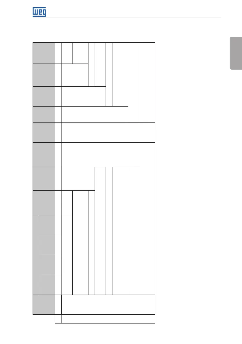
2.3 IDENTIFICATION
Table 2.1: Identification of the CFW701 inverters
Product
and
Series
Model Identification
Braking
(1)
Enclosure
(1)
Conducted
Emission
Level
(1)
Discon.
Switch
(5)
Safety
Stop
(3)
External
Control
Voltage
Special
Hardware
Version
Special
Software
Version
Frame
Size
Rated
Output
Current
Number
of Power
Phases
Rated
Voltage
Eg.: CFW701 A 03P6 T 4 DB 20 C3 DS Y1 W1 --- --
Available options
CFW701
Refer to Table 2.2 on page 6.
Blank = not available
DS = with discon. switch
Blank =
standard.
NB = without dynamic braking (valid only for frame size E
inverters and 500...600 V models of frame size D).
Sx =
special
software.
DB = with dynamic braking. Blank = standard.
20 = IP20
(2)
Hxx or Kxx = special
hardware.
21 = IP21 (not available for frame size E inverters). Blank = not available.
N1 = Nema1 enclosure (UL Type 1) (protection degree according to
IEC: IP21 for frame sizes A, B and C and IP20 for frame sizes D and E).
W1 = 24 Vdc power supply,
independent of the control
voltage.
55 = IP55 (only for 200...240 V and 380...480 V models of frame sizes
B, C, D and E).
Blank = not available.
C3 = according to category 3 (C3) of IEC 61800-3, with built-in C3 RFI filter.
(4)
Y1 = with STO function (Safe Torque Off)
according to EN 954-1/ISO 13849-1,
category 3.
Notes:
(1) The options available for each model are shown in Table 2.2 on page 6.
(2) This option is not available for 200...240 V and 380...480 V models of frame size D inverters (the standard product is Nema1).
(3) This option is not available for frame size A inverters with N1 (Nema1 enclosure) or IP21 options.
(4) It is possible to meet the requirements of category C2 with this filter on frame size A models. For further details, see Table B.7 on page 168.
(5) Only applicable to models with degree of protection IP55.