4 | CFW701
English
General Instructions
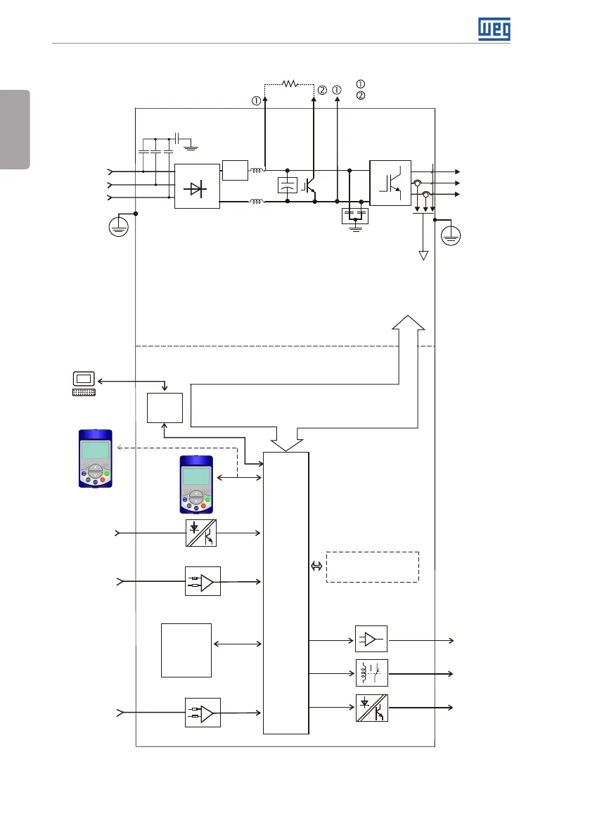
The main components of the CFW701 can be viewed in Figure A.1 on page 140.
Analog
inputs
AI1 to AI3
PTC
protection
input
FLASH
memory
module
(Slot 5)
Digital inputs
DI1 to DI8
Control power supply and interfaces
between power and control
RS-485
PC
POWER
CONTROL
Three-phase
rectifier
C3 RFI filter
(*)
Motor
U/T1
V/T2
W/T3
DC+ DC-BR
Inverter
with
IGBT
transistors
Mains power
supply
R/L1/L
S/L2/N
T/L3
= DC link connection
= Braking resistor connection
Pre-
charge
WPS software
WLP software
DC link chokes
DC link capacitor bank
Braking IGBT (available in
CFW701...DB... inverters)
RFI filter
Keypad
CC701
Control
board
with a
32 bits
"RISC"
CPU
Analog
outputs
AO1 and AO2
Digital outputs
DO1 (RL1) and
DO2 (RL2)
Digital outputs
DO3 to DO5
Keypad
(remote)
Feedback:
- voltage
- current
PE
PE
COMM 1
(Slot 3 - green)
Accessories
= Keypad (HMI)
(*) The capacitor to the ground of the C3 RFI filter (it is possible to meet the requirements of category C2 with this
filter on frame size A models) must be disconnected for IT networks and grounded delta power supplies. Please refer
to Item 3.2.3.1 Input Connections on page 14.
Figure 2.1: Block diagram for the CFW701