14 | CFW701
Installation and Connection
English
Input fuses
The fuses to be used at the input must be HS (High-Speed) type with I
2
t equal or lower the
value indicated in the Table B.1 on page 151, Table B.2 on page 152 and Table B.3 on
page 153 (consider extinction current value in cold situation (it is not the fusion value)), to
protect the inverter diode rectifiers and input wiring.
In order to meet UL requirements, use class J fuses at the inverter supply with a current not
higher than the values presented in Table B.1 on page 151, Table B.2 on page 152 and
Table B.3 on page 153 .
Optionally, slow blow fuses can be used at the input. They shall be sized for 1.2 x the rated
input current of the inverter. In this case, the installation is protected against short-circuit, but
not the inverter input rectifier. This may result in major damage to the inverter in the event of
an internal component failure.
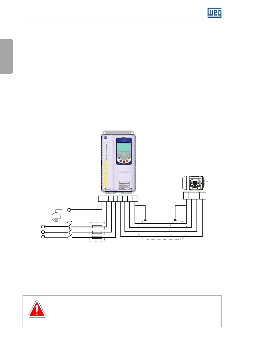
3.2.3 Power Connections
Shielding
PE
Disconnect
switch
Fuses
R
S
T
Power
supply
PE W V U
PE R S T U V W PE
Figure 3.2: Power and grounding connections
The switch-disconnector is not necessary if the inverter has the DS optional item (with switch-
disconnector).
3.2.3.1 Input Connections
DANGER!
Provide a disconnect device for the input power supply of the inverter.
This device shall disconnect the input power supply for the inverter when needed
(for instance, during servicing).