CFW701 | 7
English
General Instructions
2.4 LIST OF AVAILABLE MODELS
The available inverter models are listed in Table B.1 on page 151, Table B.2 on page 152
and Table B.3 on page 153.
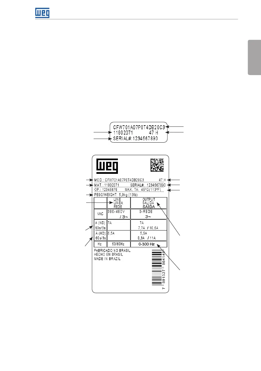
2.5 IDENTIFICATION LABELS
There are two nameplates on the CFW701: one complete nameplate is affixed to the side of the
inverter and a simplified one is located under the keypad. Please refer to Figure A.2 on page
141 to verify the position of these labels on the product. The nameplate under the keypad
allows the identification of the most important characteristics of the inverter even if they are
mounted side-by-side. When there is more than one inverter it is necessary to be careful not to
exchange the inverter covers (front cover in case of inverters frame sizes A, B or C and control
rack cover for inverters frame sizes D and E) because there are individual information labels
under the keypad of each inverter.
CFW701 model
Manufacturing dateWEG part number
Serial number
(a) Nameplate located under the keypad
CFW701 model
WEG part number
Manufacturing date
Inverter net weight
Input rated data (voltage,
number of phases, rated
currents for operation
with ND and HD overload
cycles, and frequency)
Output rated data (voltage,
number of phases, rated
currents for operation with
ND and HD overload cycles,
overload currents for 1 min
and 3 s, and frequency range)
The maximum output
frequency depends on the
settings of the motor rated
frequency, control mode and
inverter switching frequency.
For further details, see Table
B.1 on page 151.
Maximum ambient
temperature (without
derating) for ND overload
with open spaces for
ventilation around the
inverter (refer to the
dimensions A, B, C and D in
Figure B.3 on page 176)
Serial number
Current specifications
for operation with normal
overload cycle (ND)
Current specifications
for operation with heavy
overload cycle (HD)
(b) Nameplate affixed to the side of the inverter
Figure 2.2: (a) and (b) Nameplates