上海维宏电子科技股份有限公司
SHANGHAI WEIHONG ELECTRONIC TECHNOLOGY CO., LTD.
2 / 97
1.1.1 Schematic Diagram
This schematic diagram of NK105 (E) control box with four axes is as follows:
1. USB interface
It allows NK105 to communicate with other devices.
2. DB15 interface
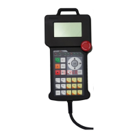
It is used to connect to a handheld box.
3. +24V IN input interface
It is used to connect to a 24V DC power supply.
4. GND
It is used to connect to the port GND or COM of a DC power supply.

 Loading...