9
Indicator Technical Manua
Load Cell Wiring
1. Ensure the unit is not plugged in or powered on.
2. Run the cable from the load cell or junction box through the strain-relief
and wire the indicator power to the Load Cell Terminal Block. See table
below:
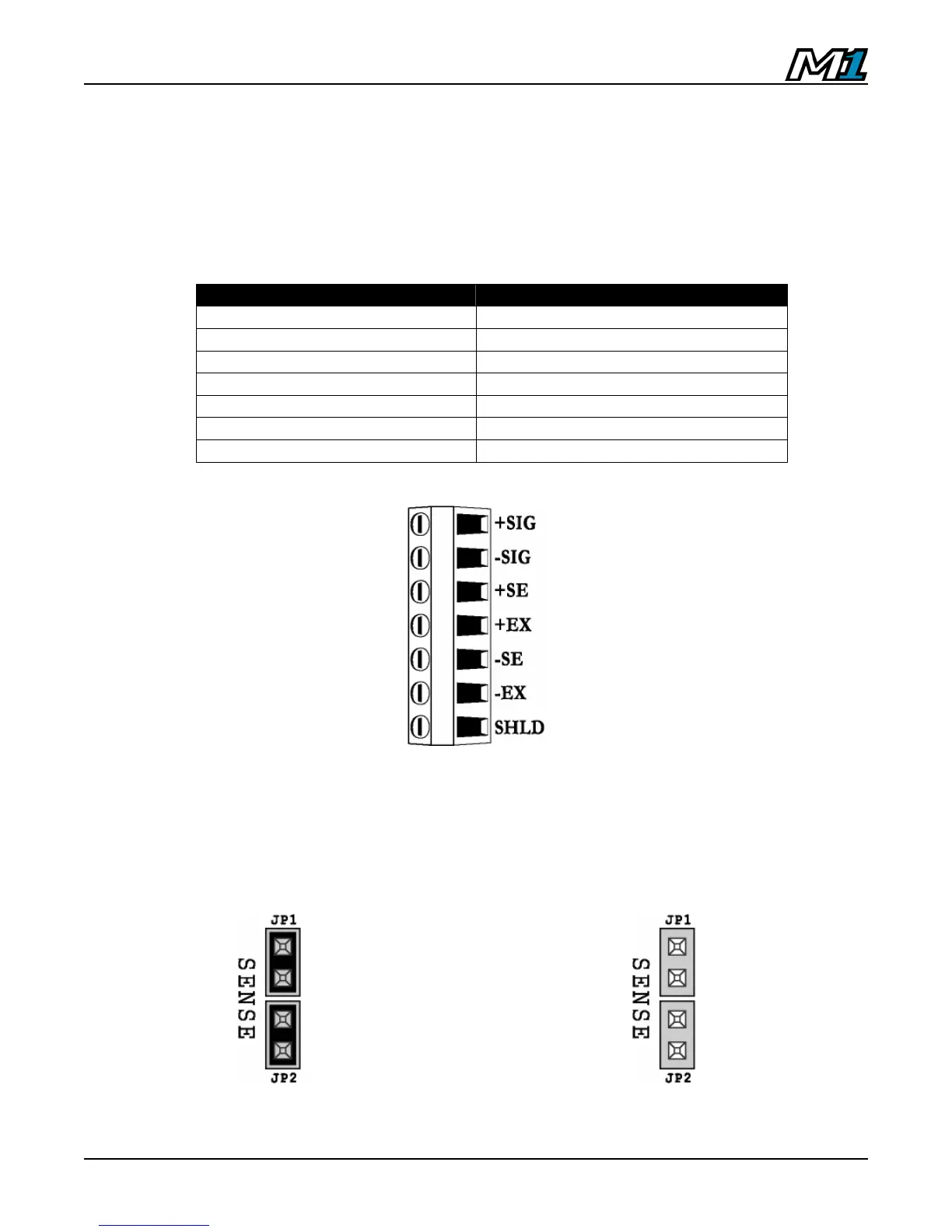
LOAD CELL TERMINAL LOAD CELL WIRE
+EXC Positive Excitation
+SNS Positive Sense
+SIG Positive Signal
SHLD Shield Wire
-SIG Negative Signal
-SNS Negative Sense
-EXC Negative Excitation
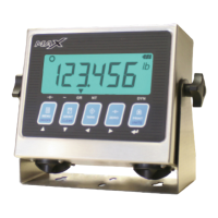
Load Cell Jumpers
The M1 accommodates 4 or 6 wire load cells. When using 4 wire load cells (No
SENSE wires), the pins on JP1 and JP2 must be jumpered. For 6 wire load
cells, remove the jumpers. See illustration below:
4 wire load cell – Jumpers ON
6 wire load cell – Jumpers OFF
Load Cell Terminal Block