8
Indicator Technical Manua
INSTALLATION
Pre-Installation
It is always good practice to verify that your Western M1 indicator is complete
and undamaged upon receipt.
• Check over packaging for any signs of damage.
• Remove M1 from protective packaging and check for damage.
• Verify that the box includes the M1 indicator complete with:
o User Manual;
o Mounting bracket and thumb screws.
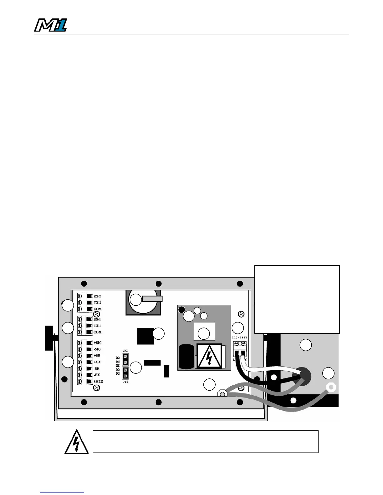
Opening the M1 Enclosure
1. Make sure the unit is disconnected from power.
2. Remove the screws from the back of the enclosure.
3. Lift the back cover away from the enclosure. Be sure to observe proper
ESD procedures when handling PCBs.
1. M1 PCB
2. Power Supply Module
3. Load Cell Terminal Block
4. Load Cell Jumpers (Sense)
5. Com1 Terminal Block
6. Com2 Terminal Block
7. 90 - 240 VAC Terminal Block
8. Grounding Posts
9. Back Cover (w/ Strain-reliefs
and power cable
10. Batter
1 2
6
5
4
7
8
9
3
8
CAUTION! HIGH VOLTAGE! Only trained personnel should
access any internal wiring and/or components.
10