18
WIKA operating instructions process transmitter, model UPT-2x
14111166.02 04/2015 EN/DE
EN
5. Commissioning, operation
5.2.3 Requirements regarding intrinsic voltage supply
■
Power the process transmitter via an intrinsically safe circuit (Ex ia). Both the internal
capacitance and inductance must be considered (→ see chapter 15 “Specications”).
■
Provide the required voltage supply separation between Ex and non-Ex areas
with a certied isolated barrier or Zener barrier (suitable isolated barrier, model
KFD2-STC4-Ex1).
■
For applications that require EPL Gb or Db, the power supply and signal circuit should
have a protection level of “ib”. Then the interconnections and the transmitter will have
a protection level of II 2G Ex ib IIC T4/T5/T6 Gb or II 2D Ex ib IIIC T4/T5/T6 Db, even if
the process transmitter is marked otherwise (→ see EN 60079-14 section 5.4).
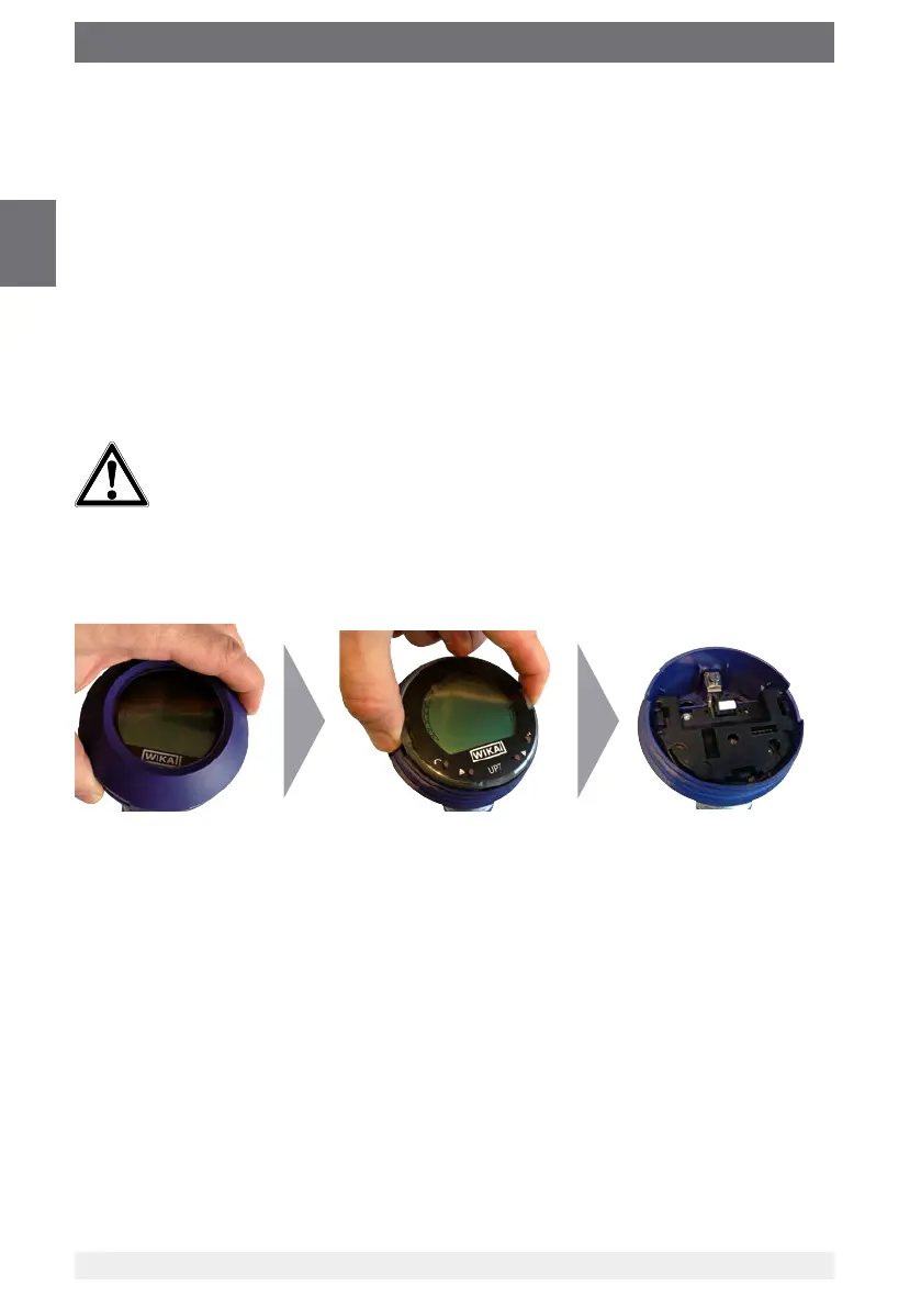
5.2.4 Opening the case
CAUTION!
Ingress of moisture
Moisture can destroy the process transmitter.
▶
Protect the opened process transmitter against moisture.
▶
Screw off the case head cover by hand and pull out the display and operating unit or
push-on cap.
5.2.5 Shielding and grounding
The process transmitter must be shielded and grounded in accordance with the ground-
ing concept of the plant.
▶
Connect the cable shield with the equipotential bonding.
▶
Connect the process connection or the external grounding screw with the equipoten-
tial bonding

 Loading...