English
16 WILO SE 04/2011
6.2 Example installation with the dynamic pressure
system (fig. 2)
A: Level OFF
B: Level ON
C: High water level
1: Pump with pipework
2: Pressure transducer (bell)
1)
3: Plastic hose
1)
4: Bracket
1)
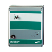
5: Switchgear EC-Drain PD1
6: Power cable for switchgear
7: Connection line to pump
1)
Accessories, see 5.4
The pressure transducer (2) measures the liquid
level from a rise in pressure. The pressure trans-
ducer is linked to the switchgear (8) via a plastic
hose (3).
The level value can be detected by two different
methods:
• Closed measuring bell with bellows,
• open measuring bell,
The activation and deactivation point of the pump
is fixed defined from the switchgear software.
Standard setting:
• Activation point = 10 cmWS
• Deactivation point = 5 cmWS
Depending on the height at which the measuring
bell is suspended in the shaft, the user is able to
determine the activation point. Potentiometers
can be used to set the pump follow-up time and
the level for the high water alarm.
To increase security, a high water float switch can
also be connected in parallel to the dynamic pres-
sure system. If the additional high water float
switch trips, optical and acoustic alarm signals are
output and the collective fault signal contact
(SSM) is active. A forced switch-on of the pump
also takes place.
6.3 Installation example with float switches (fig. 3)
A: Level OFF
B: Level ON
C: High water level
1: Pump with pipework
2: Float switch
2)
2)
Accessories, see 5.4
The liquid level is detected electrically by up to
two float switches (2).
The levels are permanently defined by the posi-
tioning of the corresponding float switches in the
sump. It is also possible to use fewer float
switches.
6.4 Function and operation
After connecting the switchgear to the supply
voltage, as well as after every mains interruption,
the switchgear returns to that operating mode
which was set before the voltage interruption.
First, all LEDs are actuated for about 2 s for testing
purposes. Afterwards, the switchgear is ready for
operation.
6.4.1 Switchgear operating elements (fig. 1)
Buttons:
Manual mode (item 1)
By pressing the manual mode button, the pump is
switched on, independent of the float switch sig-
nal, along with all safety functions, such as the
electronic motor protection and the winding pro-
tection monitor of the WSK.
The green LED “Automatic mode” (item 5) flashes
quickly and the yellow LED “Pump operation”
(pos. 6) is lights continuously. The pump is auto-
matically switched off after 2 mins. or by pressing
the STOP button (item 2).
This function is intended for commissioning or
testing purposes.
Stop (item 2)
If the Stop button is pressed, automatic or manual
mode is switched off and the green LED (item 5)
flashes slowly.
The pump is not switched on automatically. Once
the high water level is reached, optical and acous-
tic alarm signals are given and the collective fault
signal contact is active.
Automatic mode (item 3)
In automatic mode, the pumps are controlled
depending on the float switch signal or the level of
the measuring bell.
When the switch-on level has been reached, the
float switch contact is closed and the pump is
switched on when using the float switch.
The yellow LED (item 6) lights up continuously.
If the switch-off level is reached, the float switch
contact opens and the follow-up time set via the
potentiometer (fig. 4 and fig. 5, item 2) takes
effect.
The green LED (item 6) flashes until the set time
has elapsed. After the time has elapsed, the pump
switches off.
In automatic mode, all pump safety functions,
such as the electronic motor protection and WSK
monitoring, are active. In the event of a malfunc-
tion, optical and acoustic alarm signals are output
and the collective fault signal contact (SSM) is
active.
Once the high water level is reached, optical and
acoustic alarm signals are output and the collec-
tive fault signal contact (SSM) is active. In addi-
tion, there is a forced switch-on of the pumps to
increase system safety.