Access & Removal CT Hoods and DD Ventilation
4-11
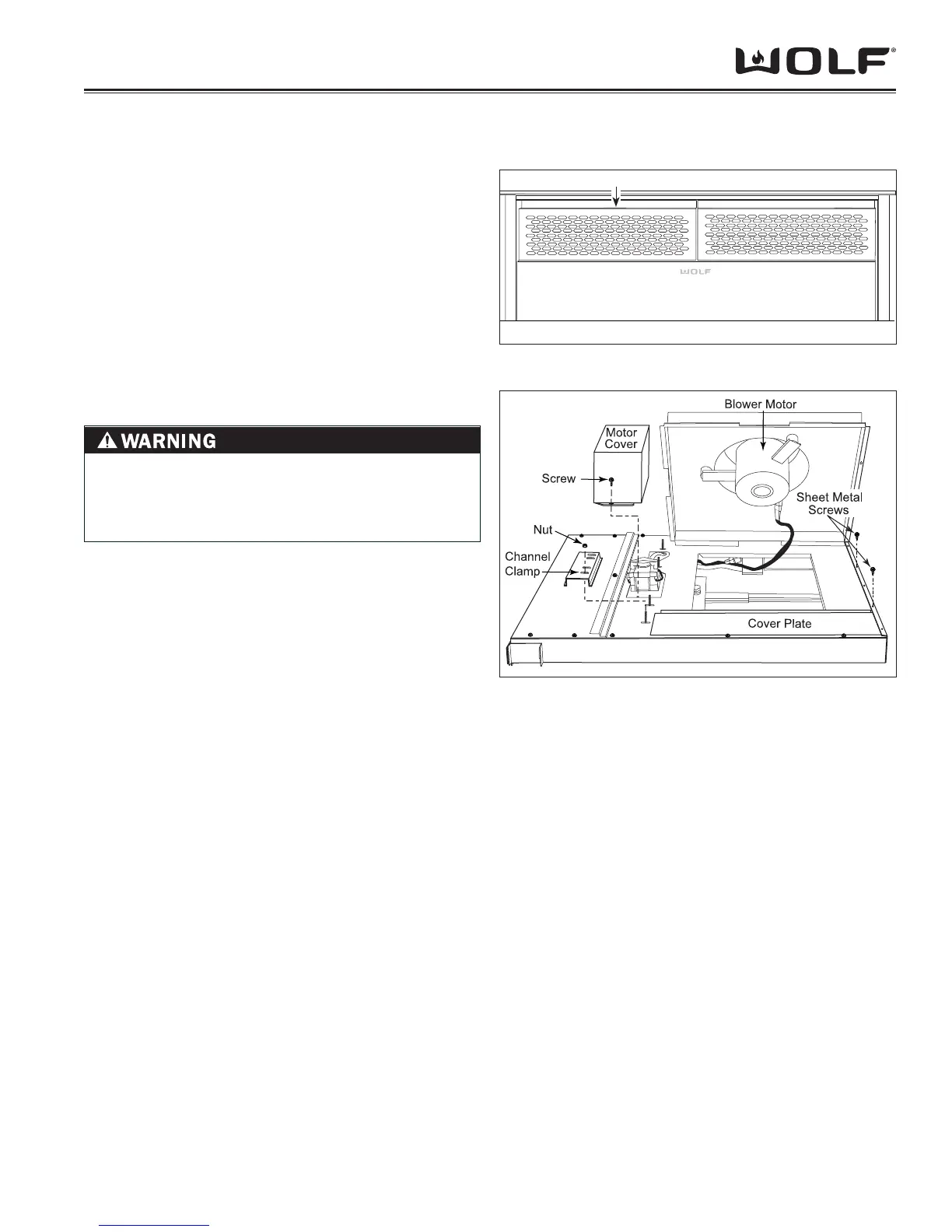
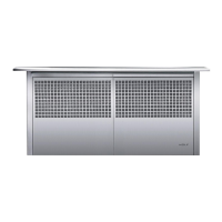
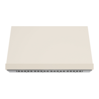
FILTER REMOVAL
NOTE: Refer to all WARNINGS and CAUTIONS at be-
ginning of this section.
The fi lter assemblies are located in the chimney assem-
bly and are secured in place by spring clips. The fi lter
assemblies consist of two pieces, the fi lter grille and fi lter
insert.
To remove the fi lters, (See Figure 26):
With chimney in the up position, push down on the 1.
fi lter frame while pulling the fi lter out away from the
downdraft.
The fi lter and fi lter grille are separated by simply pull-2.
ing the fi lter out of the fi lter grille.
I
NTERNAL BLOWER ASSEMBLY REMOVAL
In order to access the interior components, the blower
motor assembly must be removed from its installation
position. The blower motor assembly can be removed as
a unit.
To remove an internal blower motor assembly, (See
Figure 27):
Remove 3/8” (9.5) nuts from channel clamps. The 1.
channel clamps secure the cover plate and fl ange of
internal blower assembly to the downdraft frame.
Extract screws securing motor cover to downdraft 2.
frame. Remove motor cover from unit.
Extract sheet metal screws from bottom edge of 3.
downdraft that secure the internal blower assembly to
the downdraft frame.
Lift internal blower assembly up until fl ange is clear 4.
of downdraft frame. Turn internal blower assembly to
side until the wire harness is accessible. Disconnect
wire harness at quick disconnect.
Remove internal blower from unit.5.
COMPONENT ACCESS AND REMOVAL FOR MODELS DOWNDRAFT UNITS
Figure 4-26 Filter Removal
Figure 4-27 Internal Blower Assembly Removal
Push down here
TO AVOID ELECTRIC SHOCK, POWER TO THE
VENTILATION UNIT MUST BE DISCONNECTED
WHENEVER PERFORMING THE FOLLOWING
REPAIR.