Assembly 29
32394 (Rev. 9/3/2004)
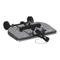
Figure 19. Blade Assembly
REAR DRIVE & SLIP CLUTCH
INSTALLATION
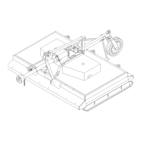
Figure 20. Slip Clutch Installation
Place keys (3) in input shaft of center gearbox. Install
slip clutch (1) by aligning keys and bolt hole, and slide
over shaft. Secure with bolts (5 & 7) and nuts (6 & 8).
Torque according to values given on the bolt torque
chart, page 68.
Tri-lobe and splined shaft drives install similarly to 1-
1/2" square shaft drive.
Attach clutch shield (2) to cutter frame with sheet metal
screws (4).
DB1954
1. Bolt
2. Lock clip
3. Keyhole plate
4. Spacer
5. Spacer
6. Spacer
7. Crossbar
8. Blade
9. Pin
DB2195A
1. Slip clutch
2. Clutch shield
3. Key
4. Sheet metal screw
5. 7/16 x 3-1/2 Bolt
6. 7/16 Locknut
7. 5/8 NC x 3-1/2 Hex
head cap screw
8. 5/8 NC Hex nut
9. Tri-lobe drive
(mounted)
10. Splined drive
(pull-type)