2 Introduction
32394 (Rev. 9/3/2004)
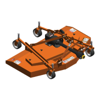
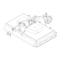
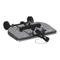
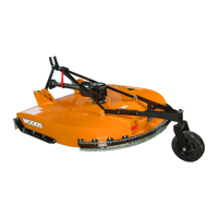
SPECIFICATIONS
M208-2 M208-2
208-2 Mounted Mounted
Pull-Type
(Single Tailwheel) (Dual Tailwheel)
Recommended Tractor Size 40-80 HP 60-80 HP 60-80 HP
Weight (Approximate) 1650 lbs. 1400 lbs. 1460 lbs.
Wheel Size 15" Rims or 16" 16" OD Solid 16" OD Solid
OD Solid Tires Caster Wheel Caster Wheel
Wheel Tread Adjustable Non-Adjustable Non-Adjustable
208-2 Pull-Type and M208-2 Mounted
Blades, Heat-Treated Alloy Steel 3/8" x 4"
Blade Rotation Direction Left Spindle: CCW Right Spindle: CW
Blade Tip Speed (ft./minute) 540 RPM = 13,520
Cutting Height Range 2 to 12 inches
Cutting Swath 8 ft. (96") (4-1/4" overlap)
Driveline Cat IV Joint with slip clutch and torsion bar protection
Gearbox Rating (Spindle Boxes) 80 HP with heat-treated alloy steel gears, heat-treated
vertical shafts and lubricated tapered roller bearings
(Input Box) 80 HP
Function The 208-2 & M208-2 model cutters are designed for mowing
large areas of grass, crop residue or brush up to 1-1/2"
diameter.
GENERAL INFORMATION
The purpose of this manual is to assist you in operating
and maintaining your cutter. Read it carefully. It fur-
nishes information and instructions that will help you
achieve years of dependable performance. These
instructions have been compiled from extensive field
experience and engineering data. Some information
may be general in nature due to unknown and varying
operating conditions. However, through experience
and these instructions, you should be able to develop
procedures suitable to your particular situation.
The illustrations and data used in this manual were cur-
rent at the time of printing but, due to possible inline
production changes, your machine may vary slightly in
detail. We reserve the right to redesign and change the
machines as may be necessary without notification.
■ Some illustrations in this manual show the cut-
ter with safety shields removed to provide a better
view. The cutter should never be operated with any
safety shielding removed.
Throughout this manual, references are made to right
and left direction. These are determined by standing
behind the equipment facing the direction of forward
travel. Blade rotation is clockwise (right) and counter-
clockwise (left) as viewed from the top of the cutter.
WARNING