ELECTRICAL SYSTEM
STW34, STW37, STW40, WSM
9-S21
Travelling Speed Sensor
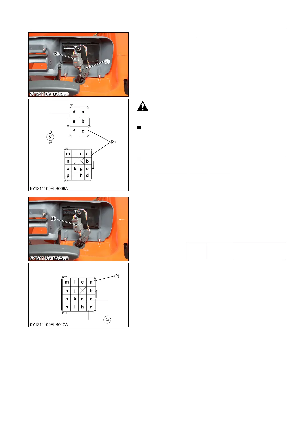
1. Disconnect the connectors (1), (2).
2. Jack up the rear wheels and shift the front wheel drive lever to
OFF position.
3. Start the engine and turn the rear wheel as following condition.
• Range shift lever: 1
• Cruise control lever: 2 notch
• Engine speed: around 1000 min
-1
(rpm)
4. Measure the travelling speed sensor voltage on the connector's
terminal of wire harness side 6P connector of d terminal - 16P
terminal of p terminal.
• Be sure to disengage the front wheel drive, when checking
the travelling speed sensor with rotating the rear wheel.
• The analog type tester may not check for voltage.
• There is no need to "Fine adjustment" about travelling
speed sensor if replaced.
• Be sure to check the alternate voltage range.
9Y1211109ELS0025US0
Bi-speed Solenoid Valve
[Solenoid]
1. Disconnect the 16P connector (1).
2. Measure the bi-speed solenoid valve resistance between g
terminal (Ground) and d terminal (solenoid valve).
If the measurement is not within the factory specifications,
replace it.
9Y1211109ELS0026US0
Output alternate voltage
of travelling speed
sensor
Factory
specifi-
cation
d terminal –
p terminal
Approx. AC 1.0 V
(1) 6P Connector
(2) 16P Connector
(3) Connector (Wire Harness)
Resistance between
bi-speed solenoid valve
and ground
Factory
specifi-
cation
g terminal –
d terminal
11 to 15 Ω
(1) Connector (2) Connector (Wire Harness)



 To Next Page