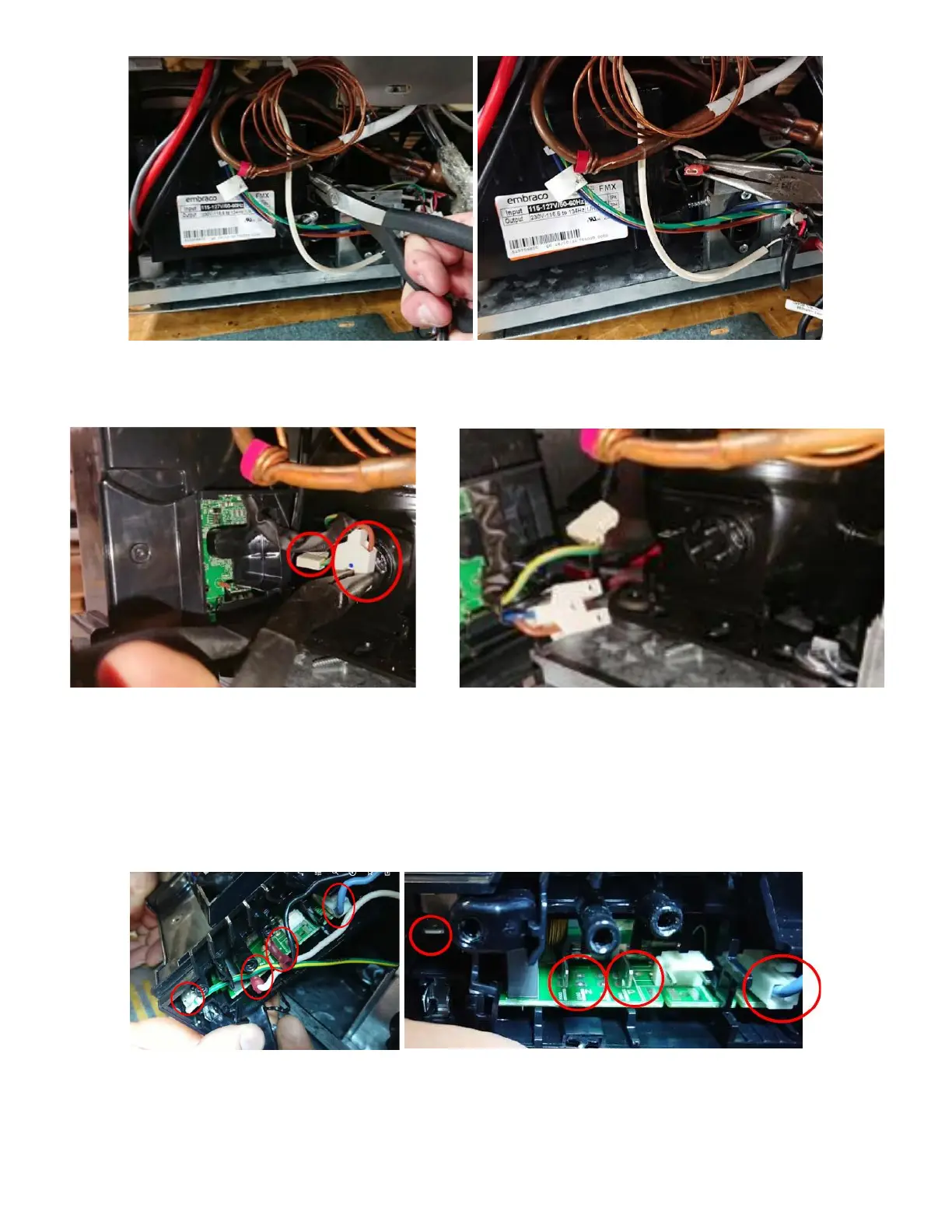
EasyManua.ls Logo

Wunder-Bar JoeTap NITCOM - Page 36

Default Icon
95 pages
Print Icon
To Next Page IconTo Next Page
To Previous Page IconTo Previous Page
Loading...
Page | 36
With a rocking motion remove the compressor connection and the compressor ground. See Figure
79a and 79b.
xii. Connect inverter wires back for testing:
Connect the following wire back up so we can test/check See Figure 80a and 80b:
a. Ground (Green W/ Yellow)
b. P Power/Line voltage (Black)
c. Neutral (white)
d. Signal (Light blue)
Again, ensuring the blue dot is present on the UI, check all three posts against the ground for voltage
(120v). See Figure 81a, 81b, and 81c.
Figure 78a: Ground wire being removed.
Figure 78: Ground Wire shown removed.
Figure 79a: Compressor connections shown.
Figure 79b: Compressor connections removed.
Figure 80a: Inverter connections shown.
Figure 80b: Inverter connections removed.

Table of Contents

Related product manuals