Page | 43
b. Peel overlay off.
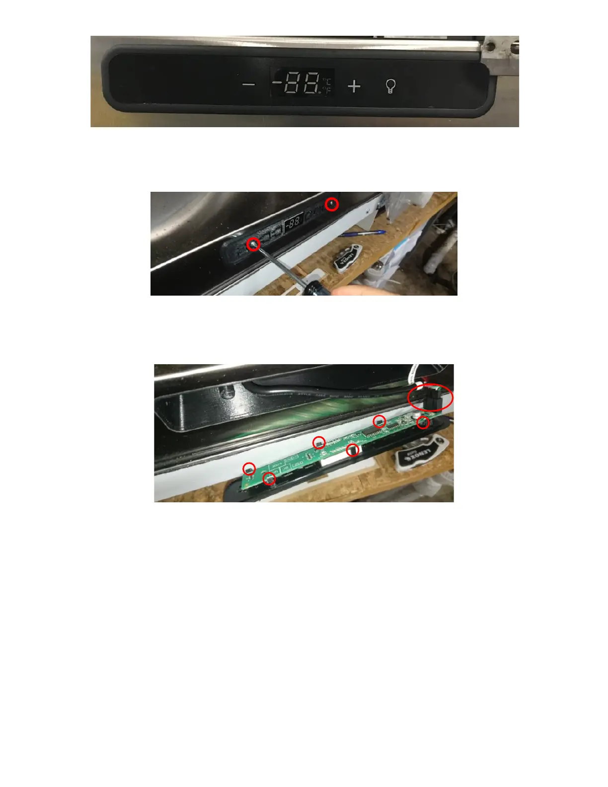
e. Remove 2 screws and pull out the Black Plastic Bracket holding the LED UI Display/Board. See Figure 94.
f. Remove LED UI Display/Board from control housing (held in place by 5 tabs) and disconnect harness. See
Figure 95.
g. Inspect Harness and verify there is no rust inside the connector pins. If connector is rusted/damaged, then
replace the UI Harness. See next step UI Harness Is Damaged.
h. If UI Harness is in good condition, plug it into the new LED UI Display/Board and verify if the UI Harness is
undamaged by plugging unit back in. If UI Board lights up then the UI Harness is not damaged. Unplug the
Unit and continue installing the new LED UI Display/Board.
i. Place LED UI Display/Board into the new Black Plastic Bracket.
j. Peel off the White Sticker on the new Black Plastic Bracket and place it into the UI Board Cavity. Ensure the
Fridge face is clean for proper adhesion. See Figure 96a.
k. Install 2 screws. See Figure 96b.