Insulation Blowing Machine M99
X-Floc Dämmtechnik-Maschinen GmbH Page 15 of 51
Rosine-Starz-Straße 12 · 71272 Renningen · Germany
Phone +49-7159-80470-30 · Fax -40 | info@x-floc.com · www.x-floc.com
4.1.2 Power Connection
The base for the electric connection is shown on the provided electrical diagram. Pay attention to the
relevant VDE-guidelines (Association for Electric, Electronic and Information Technologies), the accident
prevention regulations and operating the insulation blowing machine outside the Federal Republic of
Germany according to national regulations.
WARNING!
Warning against dangerous electrical voltage!
Damaged cable connections and touching the electric cables can lead to electrocutions and sever
injury or death.
Before starting the connection work, ensure that the machine has been assembled
correctly and the hopper [3] is fixed to the bottom of the machine [10].
Before operating the electric switchboard [6], move the net adaptor.
Operating the electric switch board may only be done by qualified personnel.
Before starting the connection work, the electrical installation requirements must be checked over.
The machine is not protected against long periods of continuous overvoltage. In order to avoid damaging
the machine, the existing power network’s connection value must be sufficient for the whole system. The
machine’s connection may only be made over a particular supply point, in the worksite power distribution
point. If the mains voltage is too low and the supply cables are inadequately dimensioned, the machine’s
overall power can be reduced.
When using the cable reel, care must be taken to ensure that these are fully laid out. There is a risk of
overheating and fire! Take local conditions into account and prevent the supply cable from being damaged
when laying them out. The operating personnel must not be obstructed.
The insulation blowing machine M99 requires a power supply of 230
V / 50
Hz (M99), 230
V / 50-60
Hz (M99-
DS/M99-DS-Pro). The connection is made via the three-phase supply. The supply cable must be compatible
with the H07
RNF (3× 2,5
mm) version. The protective contact must be earthed correctly, the backup fuse
must amount to 16
A. Voltage or frequency deviations of up to 5% are permissible. Connect the supply
cable to a separately secured power circuit.
Connect the net adaptor to the electrical switchboard’s [6] main connection X10 [27]. Set the blower selector
switch Q2 [20] to position “2“(M2, M3). If there is a lack of power or the performance requirements are lower
than is normally required, the machine can be put into operation using only one high performance-radial
ventilator. At this connection, the backup fuse only has to be 10
A. Set the blower selector switch to position
“1” (M2).
4.1.3 Suction Hood
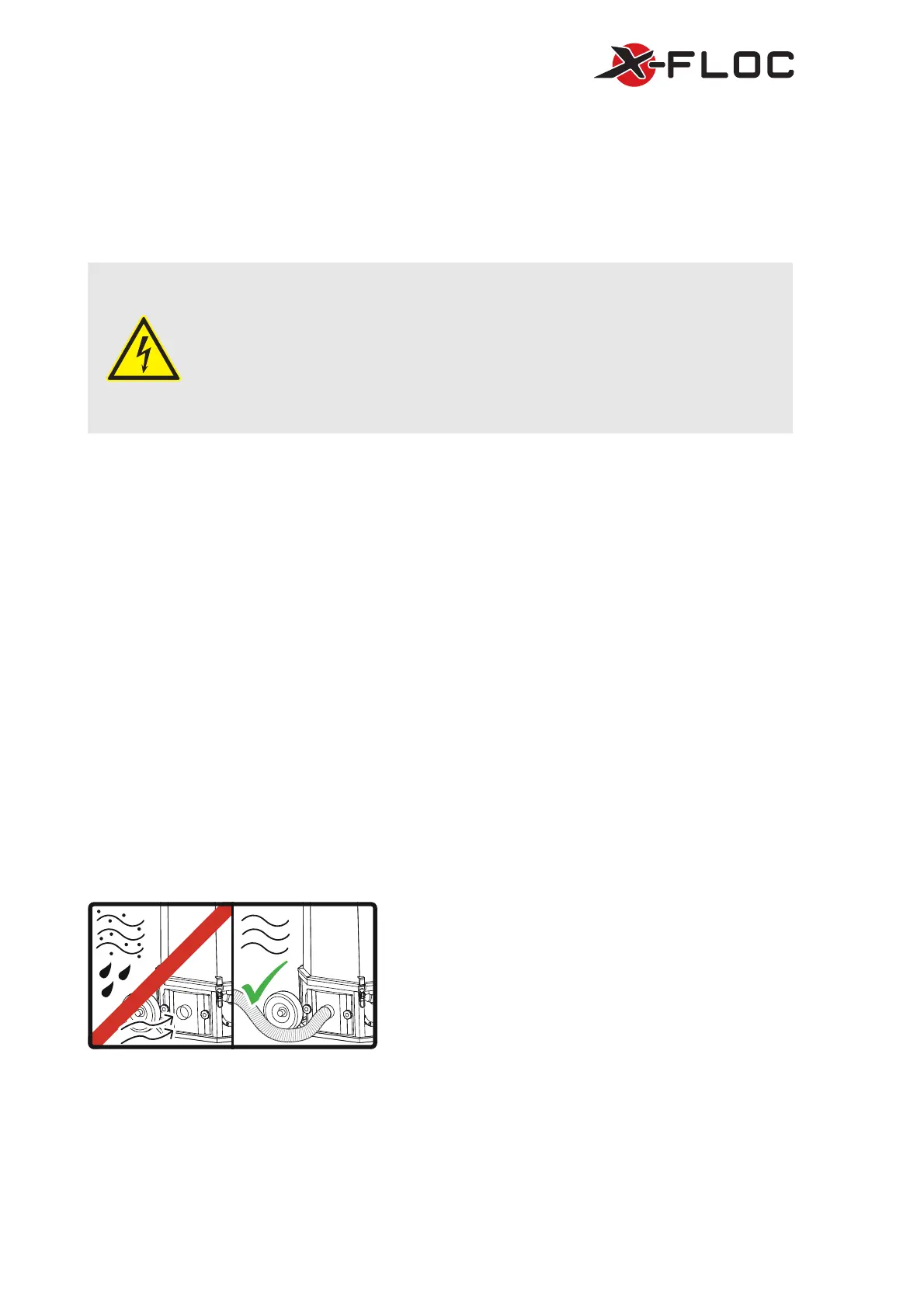
Figure 9: Incoming air through hose connection
The fresh air is vacuumed via the suction hood’s [12] intake
socket NW75 [11] and must be clean every time. If the
surrounding air’s particle load is too heavy, fresh air must
be blown into the area using the hose (up to 5m long)
provided in the delivery contents from an area with clean
air. The hose connection should be chosen so that no
material and dirt can be sucked in and hose opening can
always be seen. The hose connection should regularly be
checked for dirt and blockages and be cleaned if necessary.
The suction hose, with a nominal diameter NW75, must be
put over the intake socket and hermetically sealed with a
hose clamp NW75.
 Loading...