Insulation Blowing Machine M99
Page 30 of 51
X-Floc Dämmtechnik-Maschinen GmbH
Rosine-Starz-Straße 12 · 71272 Renningen · Germany
Phone +49-7159-80470-30 · Fax -40 | info@x-floc.com · www.x-floc.com
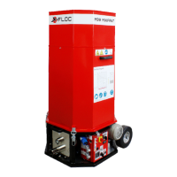
6.1.5 Pressure Test
Figure 27: Pressure gauge and outlet [7]
For pressure testing, a pressure gauge is required. Turn on the
insulation blowing machine at the main switch Q1 [19] and set the
blower power with the blower power selector R1 [23] to 100%.
Press the pressure gauge device firmly onto the machine’s
outlet [7] and read off the blowing pressure. The minimum
blowing pressure should be approx. 245
mbar.
6.1.6 Air Filter
Figure 28: Suction hood [12]
he incoming air is purified through an air filter. A heavily
contaminated air filter can significantly negative influence the air
supply unit and the machine output. For this reason, the air filter
must be checked for contamination before and after every
commissioning and if necessary be cleaned or replaced.
The air filter is located in the suction hood [12]. Open the star grip
nut and take off the suction hood. Vacuum the air filter or replace it
if there is heavy contamination. Place the suction hood back onto
the screws and fix it using the star grip nut.
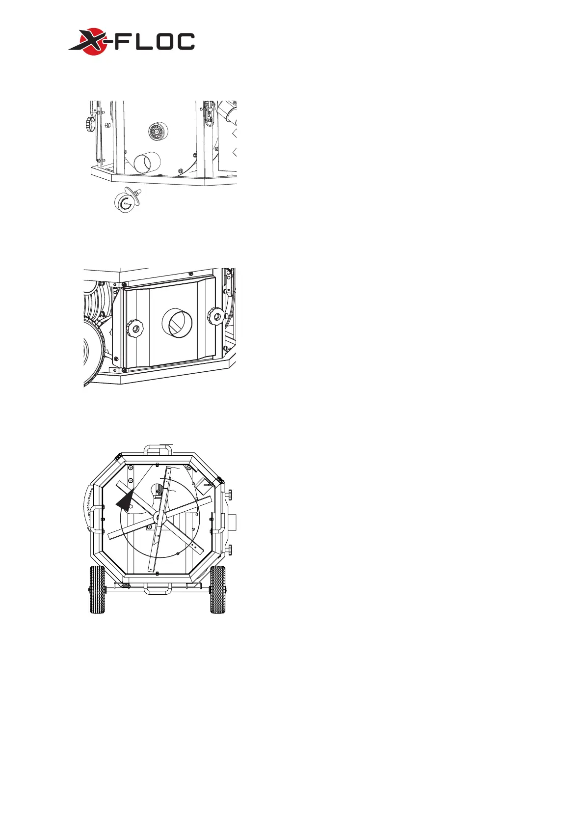
6.1.7 Conditioning Unit
Figure 29: Conditioning unit [9], top view
The conditioning unit [9] is located in the machine’s bottom [10].
A strongly deformed conditioning unit cannot shredder the
insulation material properly, meaning that blockages can arise
and machine’s functionality can be impaired.
For this, the conditioning unit must be checked for deformations
regularly for deformations and abrasion.
The conditioning unit’s arm has a fastened rubber strip which
prevents bridging and improves emptying the machine. A worn
rubber strip should be replaced. For further information, please
contact customer service.
6.1.8 Pressure Detection Unit M99-DS-Pro
In the inner side of the additional switch box [14], the pressure switch and the pressure hose can be found.
The pressure hose connects the check valve with the pressure switch. For an exact signalling when there is
over pressure, the pressure hose has to be checked in regular intervals for contamination and if necessary, be
cleaned.
Open the additional switch box’s cover by unscrewing the four screws. Loosen the female screw on the
pressure hose and disconnect the pressure hose from the pressure switch. Blow air into the pressure hose to
clean any dirt. If the contamination is very strong, the pressure hose’s connection on the check valve must be
disconnected and cleaned. For further information, please contact customer service.
 Loading...