Insulation Blowing Machine M99
X-Floc Dämmtechnik-Maschinen GmbH Page 45 of 51
Rosine-Starz-Straße 12 · 71272 Renningen · Germany
Phone +49-7159-80470-30 · Fax -40 | info@x-floc.com · www.x-floc.com
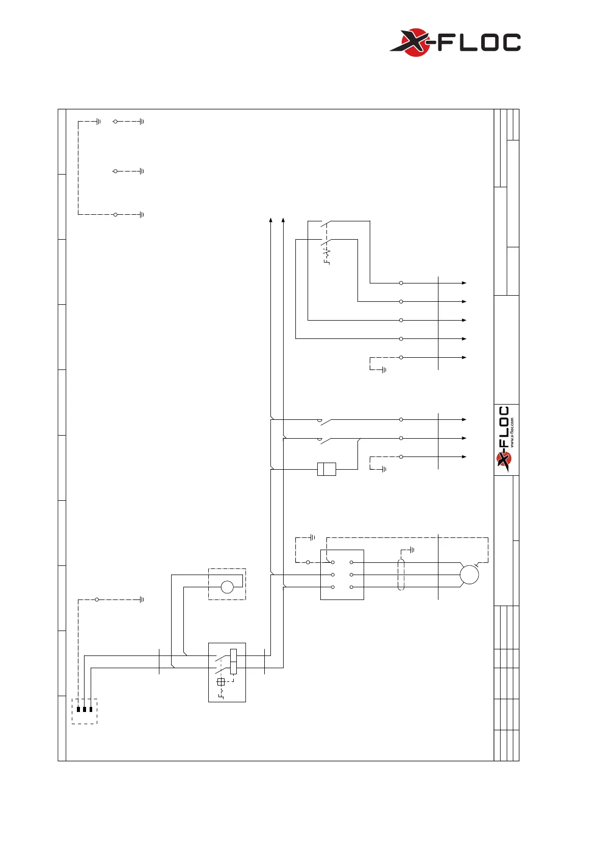
7.2.4 Electrical Circuit Diagram M99-DS-Pro
Blatt
Blatt
Minifant M99-230V/3,6kW-DS-Pro
Bearb.
Urspr
V3.1.0
+
Datum
Datum
Ersetzt durch
M99F-DS-Pro V3.0.0
K01-HS
Hauptspannungskreis
1
Änderung
0 76
Gepr
Ersatz von
893
3
4
09.06.2015
1
2
=
Name
5
MKl
L1 L2
Zu: K02-Zusatzschaltanlage
obobob
ob
un un
Hauptanschluss
3x2.5mm²
max. 35m Länge
1x1,5mm²
H07V-K 1,5 SW
UV
U< U<
-Q1
Hauptschalter
-P2
Netz-
spannungs-
anzeige
Optional
li
re
V
-T3
/5.5
/5.2
Frequenz-
umrichter
L1/R L2/S PE
UVW
V1 U1 W1
PE
-M1
0,75kW | 3,31A |
Schleuse/Rührwerk
3~
M
4x1,5mm²
1 m
YSLYCY-JZ 4 x 1,5 mm²
-W1M1
321PE
PE
1/L1
2/T1
-Q3
/5.4
3L2
4T2
-P1
Betriebs-
stunden-
zähler
h
3
L2
T2
L1
T1
-Q2
Gebläse-
wahlschalter
21
87
1x1,5mm²
X07V-K 1,5 br/ws
56
1
-X1
4 ob
13
-X1
14 15
41
-X1
2
PE PE
3x1,5mm²
1 m
YSLY-JZ 3X1,5
+K02-ZS/7.0
-W4ZS
PE 2
5x1,5mm²
1 m
YSLY-JZ 5 x 1,5 mm²
+K02-ZS/7.2
-W5ZS
24131PE
PE
Türe
PE
Seiten-
gehäuse
PE
Maschinen-
gehäuse
PE
Montage-
platte
PE
-X10
Maschinen-
anschluss-
dose
N
N
L1
PE
N
/5.0
L1
/5.0
Q3-T1 Q3-T2PE PE Q2-L1 Q2-L2 Q2-T1 Q2-T2
Figure 43: Electrical circuit diagram M99-DS-Pro
 Loading...