Remote Operation
Remote Analog Operation
Release 3.0 109
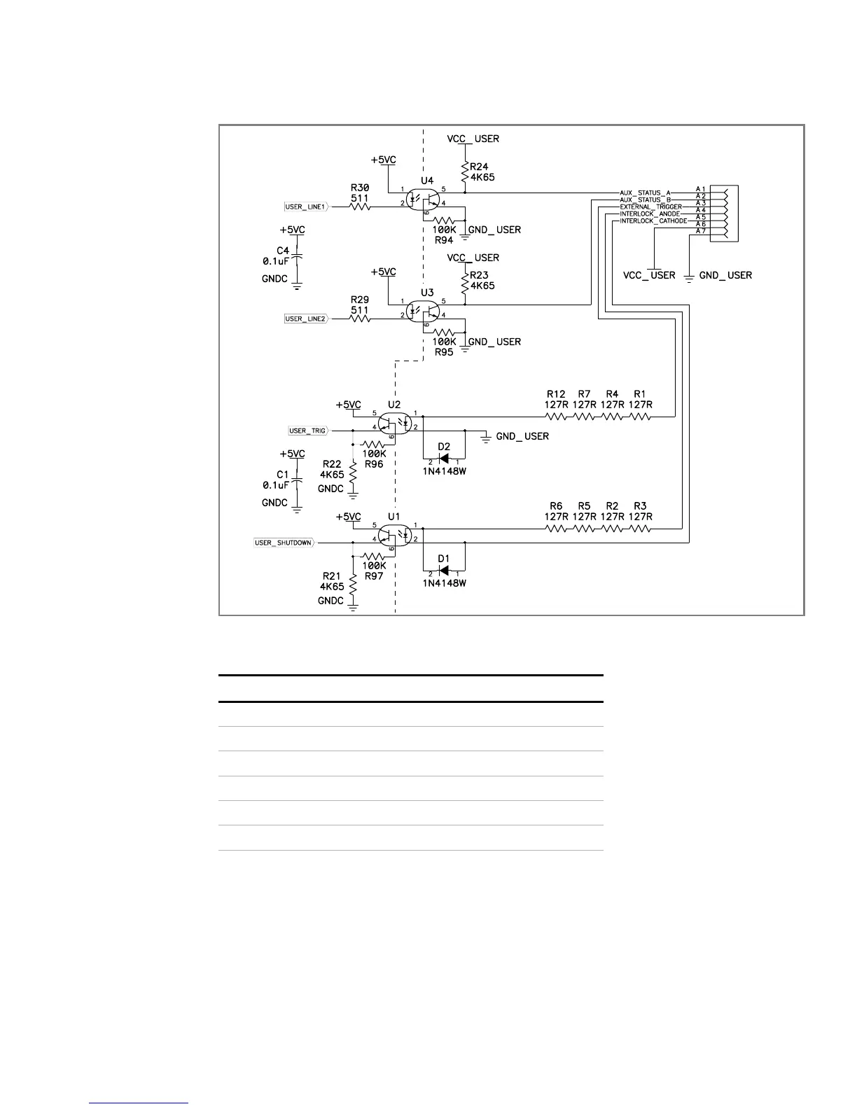
Figure 4.2 Schematic For User Line Interface
Table 4.2 Analog Programming Pins
The analog setpoint and readback pins may be configured to work in either a 0–5V
range or 0–10V range.
The programming lines have their own isolated power source (10mA max), and this
power can be looped back to power the user lines, if required. Connect the pins as
shown in Table 4.3.
Pin # Function Input/Output
B1 Analog Programming (GND) Output
B2 12V (unregulated) 10mA max Output
B3 Voltage Setpoint (0–5/10V) Input
B4 Current Setpoint (0–5/10V) Input
B5 Voltage Readback (0–5/10V) Output
B6 Current Readback (0–5/10V) Output
Vf = 1.3V TYP, 1.5V MAX
If = 10mA Recommended, 90mA MAX
CNY17-2
CNY17-2
508 Ohm
0.4W
508 Ohm
0.4W
CNY17-2
CHASSIS POTENTIAL ISOLATED USER LINES
CNY17-2
USER LINE
 Loading...