I
8a. Cover the complete surface of the
platen with white paper (20 Ib 80gsm),
then install the document handler and
rear cover.
I
9.
Enter the diagnostic mode. Select test
g,
j,
then
6
using the copy contrast
buttons. Press and hold the Start
button for one revolution of the
photoreceptor drum.
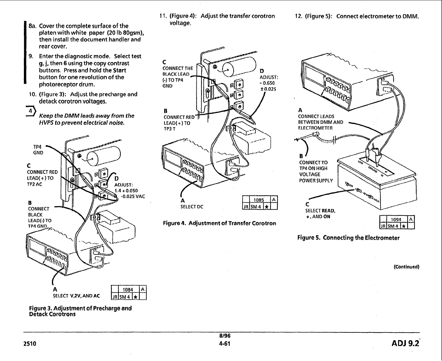
10.
(Figure
3):
Adjust
the precharge and
II
detack corotron voltages.
9
Keep the
DMM
leads away
from
the
HVPS
to
prevent electrical
noise.
CONNECT RED
A
SELECT
V.N.
AND
AC
Figure
3.
Adjustment of Precharge and
Detack Corotrons
1
1.
(Figure
4):
Adjust the transfer corotron
voltage.
CONNECT THE
CONNECT RED
A
SELECT DC
Figure
4.
Adjustmant of Transfer Corotron
12. (Figure
5):
Connect electrometer to
DMM.
CONNECT
LEADS
BETWEEN DMM AND
CONNECT TO
TP4
ON
HIGH
POWER
SUPPLY
Figure
5.
Connecting the Electrometer
8/96
2510
4-61
ADJ
9.2'
 Loading...