WARNING
(251 5
W/
Tags
2,7,
or
89):
There will be a
time delay between the time the code [A]
is
ontared and tho tlmo tho motor starts
to turn. The motor will not start until the
fuser
is
at the correct temperature.
12.
Enter diagnostic mode.
(2510,2515
WIO
Tag
2,7,
or
89)
a
Enter the code[g] and press Start.
a
Enter the code[J] and press Start.
Wait
2
Minutes.
Enter the
test
[6].
Press and hold the Start button
for more than
30
seconds to clean
the photoreceptor by engaging
the cleaner blade.
(251 5 Wl
Tag
2,7,
or
89)
Enter the test
[6].
After the drum begins rotating,
press and hold the Start button
for
30
seconds or more
to
clean
the photoreceptor
by
engaging
the cleaner blade.
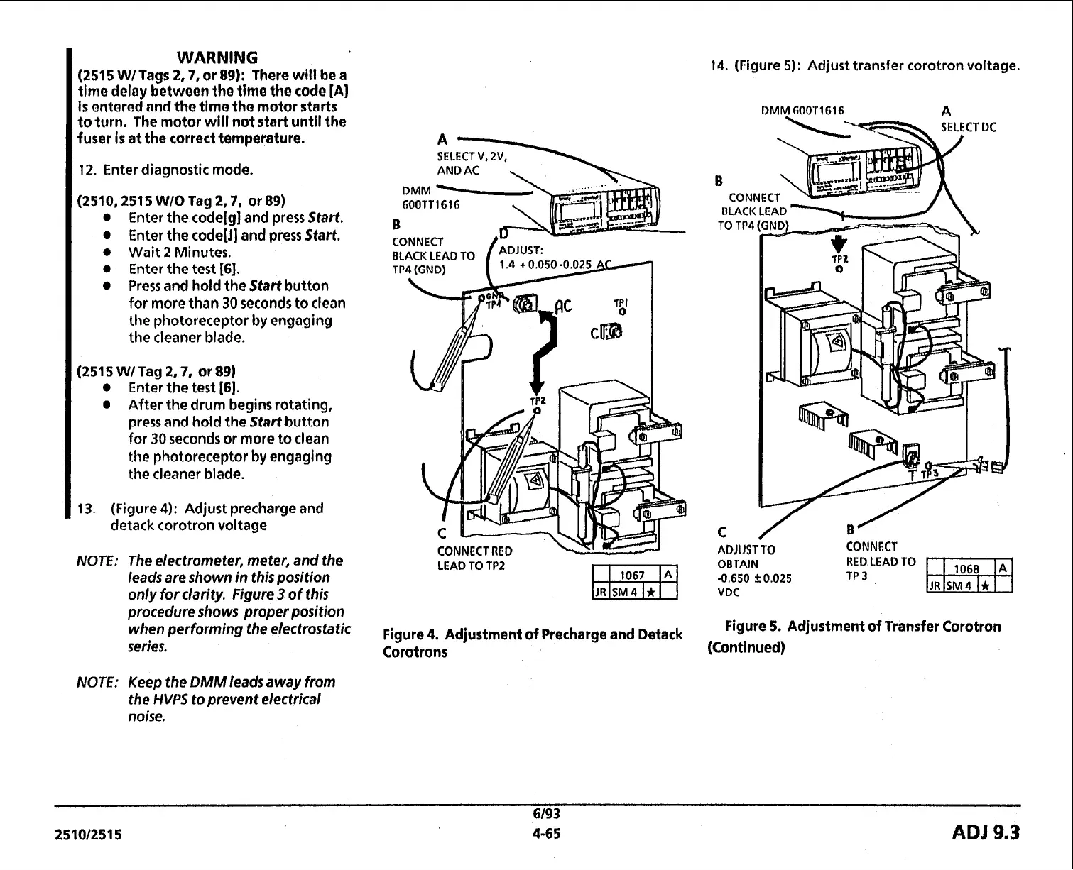
13. (Figure 4): Adjust precharge and
detack corotron voltage
NOTE: The electrometer, meter, and the
leads are shown in this position
only for clarity. Figure
3
of this
procedure shows proper position
when performing the electrostatic
series.
NOTE: Keep the
DMMleadsawayfrom
the
HVPS
to prevent electrical
noise.
SELECT
A\
V,
2V,
LEAD TO TP2
Figure
4.
Adjustment of Precharge and Detack
Corotrons
14.
(Figure
5):
Adjust transfer corotron voltage.
DMM
GOOTl616
A
.
ADJUST
TO
CONNECT
OBTAIN RED LEADTO
ml
-0.650 k0.025
TP
3
VDC
JR
SM4
Figure
5.
Adjustment
of
Transfer Corotron
(Continued)
6/93
251012515 4-65
ADJ
9.3
 Loading...