Prior to
executing
an
LRA
instruction, CC 1
and
CC2
must
be set to
an
appropriate
value
{as shown below}.
CC1
CC2
Type
of
real address to be
generated
0 0
Byte (22 bits)
0
Halfword
{21
bits}
0
Word (20 bits)
Doubleword (19 bits)
The
effective
virtual address for the
LRA
instruction
itself
may be
generated
in a normal manner (i. e.,
indirect
ad-
dressing,
indexing,
and/or
mapping,
as
applicable,
may be
specified
and performed) with
all
standard trapping
condi-
tions
in
effect.
The address loaded into
the
R register
is
dependent
upon
the
value
of
the
address portion of
the
effective
word.
Ifthe
address portion of
the
effective
word
is
equal to or
greater
than 16, it
is
converted (mapped) into a 19, 20, 21,
or
22-bit
real address, as
specified
by CC 1 and CC2.
Note:
Converting an
effective
virtual address into a real
address by mapping is performed
independently
of
the
state
of
the
map
bit
in
the
current
PSWs.
If the address portion
of
the
effective
word
is
less than 16,
it
is
not mapped into a real address. Instead, a 19,
20, 21,
or 22-bit
effective
virtual address
is
generated,
as
specified
by CC 1 and
CC2.
In
either
case a 19,
20,
21, or 22-bit real or
effective
vir-
tual address
is
loaded into a corresponding number
of
low
order
bit
positions of
the
R register {i. e., the
least
signifi-
cant
bit
of the address
is
always loaded into
bit
position
31
of
register
R}.
Except for
bit
positions
reflecting
status
in-
formation, all high
order
bit
positions within register
Rare
set
to
zero.
Contents
of
the
various
bit
positions
of
regis-
ter
R
after
an
LRA
instruction
are
as follows:
Bits
Contents
0-9
Reserved; always set
to
O.
10-31
Real or
eff~ctive
virtual address. For
21-,
20-,
and
19-bit
addresses,
as
specif,ied by
initial
value
of
CC 1 and
CC2,
bit
positions 10, 11,
and
12
will be
set
to
zeros,
as
required.
Affected: {R),CC
Condition code settings:
2 3 4 Results in R register
o 0 - -
No
abnormal condition.
- - Address in R
is
real but for a nonexistent
memory
location.
2 3 4 Results
in
R register
o 0 Address
in
R
is
an
effective
virtual
address
{address
of
a
general
register}.
- - 0
- - 0
1
1
Note:
Condition
code
setting
11--
and
1100
may be distinguished in
the
software
by examining
the
address {bits 1O-31}.
~}
Access
protect
code
for
the
page
containing
o
the
memory loc-ation
specified
by the
gener-
1
ated
address.
Note:
This instruction requires two memory
references
to
the
same
location
for its
execution.
To
preclude
other
processors from accessing
the
effective
loca-
tion during this
time,
the
memory
unit
containing
the
effective
location
is
reserved {not
accessible
to
other
processors} until
the
LRA
instruction
is
completed.
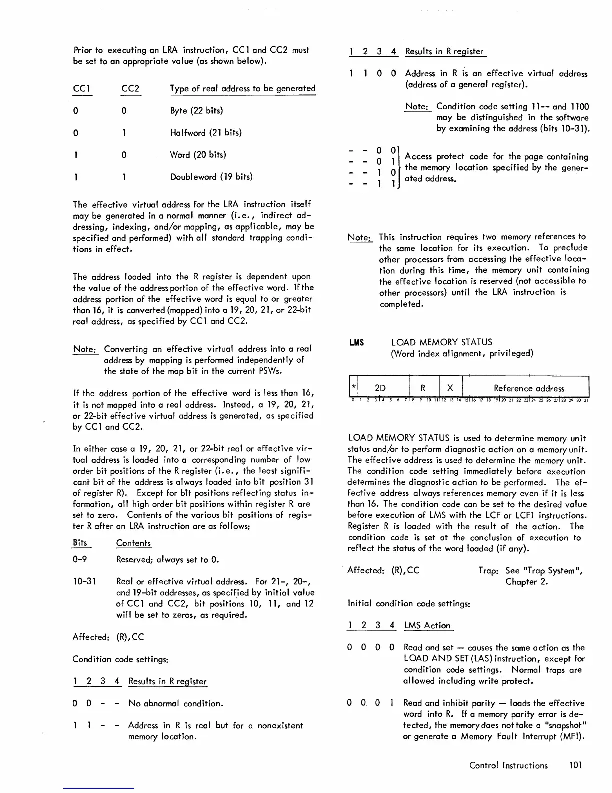
LMS
LOAD MEMORY
STATUS
(Word index al ignment,
privileged)
LOAD MEMORY
STATUS
is
used to
determine
memory unit
status
and/or
to perform diagnostic
action
on a memory
un
it.
The
effective
address
is
used to determine
the
memory
unit.
The condition code setting immediately before
execution
determines
the
diagnostic
action
to be performed. The
ef-
fective
address always references memory
even
if
it
is
less
than 16. The condition code can be set to
the
desired
value
before
execution
of
LMS
with the
LCF
or
LCFI
in§tructions.
Register R
is
loaded with
the
result of the
action.
The
condition code
is
set
at
the conclusion of
execution
to
reflect
the
status
of
the
word loaded (if
any).
. Affected: (R), CC T rap:
See
"Trap System
II,
Chapter
2.
Initial condition code settings:
2 3 4
LMS
Action
o 0 0 0 Read
and
set
- causes
the
same
action
as the
LOAD AND
SET
(LAS)
instruction,
except
for
condition code
settings.
Normal traps
are
allowed
inclUding write
protect.
o 0 0 Read
and
inhibit
parity
- loads the
effective
word into
R.
If a memory
parity
error
is
de-
tected,
the memory does
nottake
a IIsnapshot"
or
generate
a Memory Fault Interrupt (MFI).
Control Instructions
101

 Loading...


