Location
(hex)
(dec)
20
32
21
33
22
34
23
35
24
36
25
37
26
38
27
39
28
40
29
41
Hexadecimal
020000A8
o
EOOO058
22110029
64100023
68000028
OOOO####t
22000010
CCOOO025
CDOOO025
69COO022
Symbolic form
of
instruction
L1,
1
BDR,l
BCR,O
40
L1,O
SIO,O
*37
no,o *37
BCS,12 34
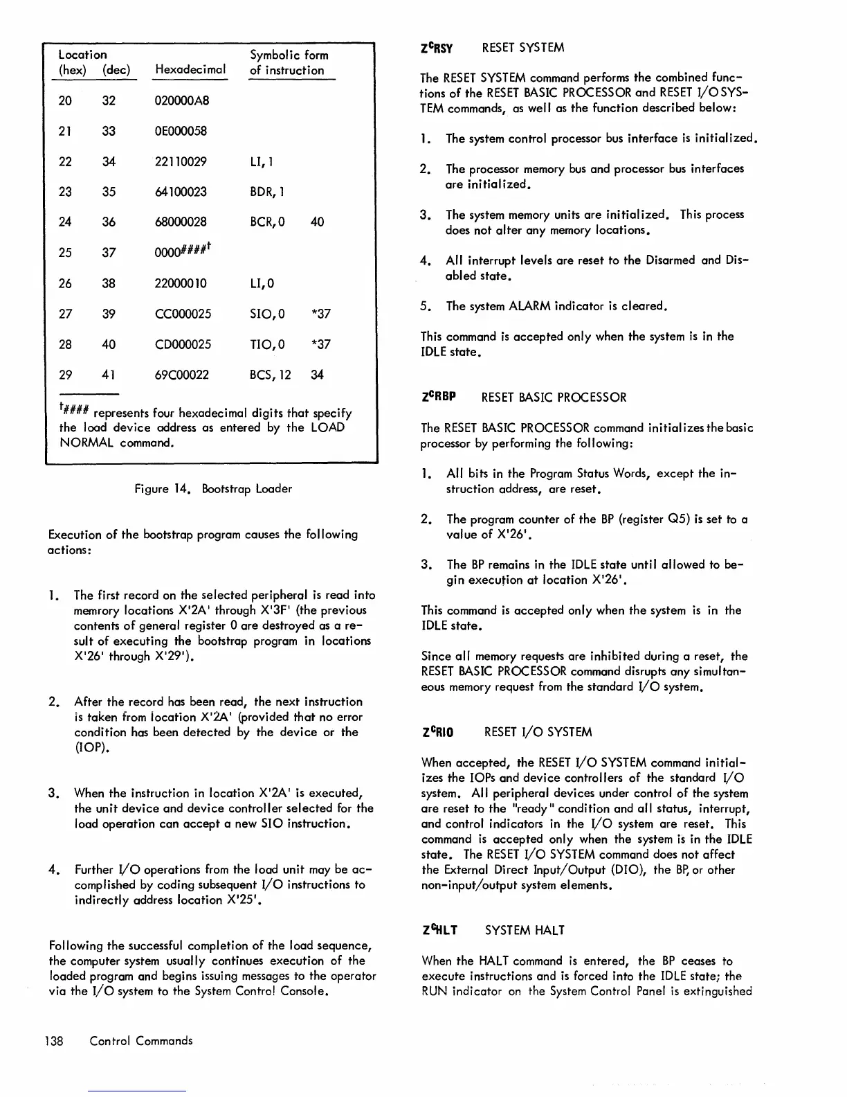
t#### represents four hexadecimal
digits
that
specify
the
load
device
address as
entered
by
the
LOAD
NORMAL
command.
Figure 14. Bootstrap Loader
Execution
of
the
bootstrap program causes
the
following
actions:
1. The first record on the
selected
peripheral
is
read into
memrory locations X'2A' through X'3F' (the previous
contents
of
general
register 0
are
destroyed as a
re-
sult
of
executing
the
bootstrap program in locations
X'26' through X'29').
2.
After
the
record has been read, the
next
instruction
IS
taken
from
iocation
X'2A' (provided
that
no error
condition
has been
detected
by the
device
or
the
(lOP).
3.
When
the
instruction in
location
X'2A' is
executed,
the
unit
device
and
device
controller
selected
for
the
load
operation
can
accept
a new
SIO
instruction.
4.
Further
I/o
operations
from
the load unit may be
ac-
complished by
coding
subsequent
I/O
instructions to
indirectly
address
location
X'25
1
•
Following
the
successful completion
of
the load
sequence,
the computer system usually continues
execution
of
the
loaded program and begins issuing messages to
the
operator
via
the
I/O
system
to
the
System Control Console.
138 Control Commands
RESET
SYSTEM
The
RESET
SYSTEM
command performs
the
combined
func-
tions
of
the
RESET
BASIC
PROCESSOR
and
RESET
I/O
SYS-
TEM
commands, as well as
the
function described below:
1. The system control processor bus
interface
is
initialized.
2.
The processor memory
bus
and
processor
bus
interfaces
are
initialized.
3.
The system memory units
are
initialized.
This process
does
not
alter
any
memory
locations.
4.
All interrupt levels
are
reset
to
the
Disarmed and Dis-
abled
state.
5.
The system
ALARM
indicator is
cleared.
This command
is
accepted
only when the system
is
in the
IDLE
state.
zCRBP
RESET
BASIC
PROCESSOR
The
RESET
BASIC
PROCESSOR command initial izes the basic
processor by performing the following:
1.
All bits in
the
Program Status Words,
except
the
in-
struction address,
are
reset.
2.
The program
counter
of
the
BP
(register
05)
is
set
to a
value
of
X'26'.
3. The
BP
remains in
the
IDLE
state
unti J
allowed
to
be-
gin
execution
at
location X'26'.
This command
is
accepted
only when
the
system
is
in the
IDLE
state.
Since
all
memory requests
are
inhibited
during a reset,
the
RESET
BASIC
PROCESSOR command disrupts
any
simultan-
eous memory request
from
the standard
I/o
system.
RESET
I/O
SYSTEM
When
accepted,
the
RESET
I/O
SYSTEM
command
initial-
izes
the
lOPs
and
device
controllers
of
the
standard
I/O
system. All peripheral devices under control
of
the
system
are
reset to
the
"ready"
condition and
all
status, interrupt,
and
control indicators in the
I/O
system
are
reset. This
command
is
accepted
only when
the
system
is
in
the
IDLE
state.
The
RESET
I/O
SYSTEM
command does not
affect
the
External Direct
Input/Output
(010),
the
BP,
or other
non-input/output
system elements.
zcttL
T
SYSTEM
HALT
When
the
HALT
command
is
entered,
the
BP
ceases to
execute
instructions and
is
forced into
the
IDLE
state;
the
RUN
indicator
on the System Control Panel
is
extinguished