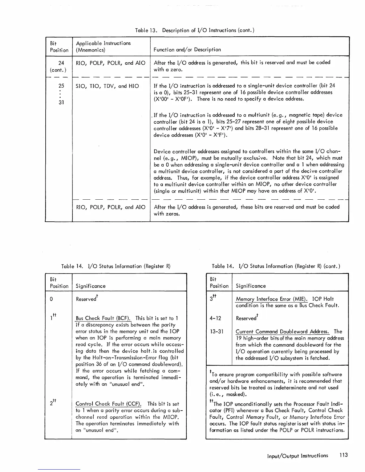
Table
13.
Description
of
I/O
Instructions
(cont.)
Bit
Applicable
Instructions
Position (Mnemonics)
Function
and/or
Description
24
RIO, POLP, POLR,
and
AIO
After
the
I/O
address is
generated,
this
bit
is reserved
and
must be
coded
(cont.)
with
a
zero.
---
f------
-
----
----------
-------
Bit
25
31
SIO,
no,
TDY,
and
HIO
If
the
I/o
instruction
is addressed
to
a
single-unit
device
controller
(bit
24
is a
0),
bits 25-31
represent
one
of
16
possible
device
controller
addresses
(X1001
- X10FI). There is no
need
to
specify
a
device
address.
_
If
the
I/O
instruction
is addressed
to
a
multiunit
(e.
g.,
magnetic
tape)
device
controller
(bit
24 is a 1), bits 25-27
represent
one
of
eight
possible
device
controller
addresses
(X101
-
X?I)
and
bits 28-31
represent
one
of
16
possible
device
addresses
(X101
-
XIP).
Device
controller
addresses assigned
to
controllers
within
the
same
I/O
chan-
nel
(e.
g.,
MIOP),
must
be
mutually
exclu~;ve.
Note
that
bit
24,
which
must
be a
0 when addressing a
single-unit
device
controller
and
a 1 when addressing
a
multiunit
device
controller,
is
not
considered
a
part
of
the
decive
controller
address. Thus, for
example,
if
the
device
controller
address
X101
is assigned
to
a
multiunit
device
controller
within
an
MIOP,
no
other
device
controller
(single or multiunit)
within
that
MIOP
may
have
an
address of
X101.
--
- - -
--
- - - - - - - - - - - - - - -
---
RIO, POLP, POLR, and
AIO
After
the
I/O
address is
generated,
these
bits
are
reserved
and
must
be
coded
with
zeros.
Table
14.
I/o
Status
Information (Register
R)
Table
14.
I/O
Status
Information (Register
R)
(cont.)
Bit
Position
Significance
Position
Significance
o Reserved
t
Bus
Check
Fault
(BCF). This
bit
is
set
to 1
if
a
discrepancy
exists
between
the
parity
error status in
the
memory
unit
and
the
lOP
when an
lOP
is performing a main memory
read
cyc
Ie.
If
the
error
occurs
wh i I e
access-
ing
data
then
the
device
halt.
is
controlled
by
the
Halt-on-Transmission-Error
flag
(bit
position
36
of
an
I/O
command
doubleword).
If
the
error
occurs
whi
Ie
fetching
a
com-
mand,
the
operation
is
terminated
immedi-
atey
with
an "unusual
end".
Control
Check
Fault
(CCF). This
bit
is
set
to 1 when a
parity
error
occurs
during a
sub-
channel
read
operation
within
the
MIOP.
I The
operation
terminates
immediately
with
I
an
"unusual
end".
i
3
tt
Memory
Interface
Error (MIE).
lOP
Halt
condition
is
the
same
as
a
Bus
Check
Fault.
4-12
13-31
Reservel
Current
Command Doubl eword Address. The
19
high-order
bits of
the
main memory address
from
which
the
command doubleword for
the
I/O
operation
currently
bei
ng
processed by
the
addressed
I/O
subsystem is
fetched.
tTo ensure program
compatibility
with possible software
and/or
hardware
enhancements,
it
is recommended
that
reserved bi ts
be
treated
as
i ndetermi
nate
and
not
used
(i.
e.
I masked).
ttThe
lOP
unconditionally
sets
the
Processor
Fault
Indi-
cator
(PFI)
whenever
a
Bus
Check
Fault,
Control
Check
Fault,
Control Memory Fault, or Memory
Interface
Error
occurs. The
lOP
fault
status
register
isset
with
status
in-
formation
as
listed under
the
POLP or POLR instructions.
Input/Output
Instructions
113

 Loading...


